Connecting offices (site-to-site)
- PPTP VPN
- Incoming Connection of Cisco IOS to SafeUTM via IPsec
- Outgoing SafeUTM Connection to Cisco IOS via IPsec
- Incoming pfSense connection to SafeUTM via IPsec
- Outgoing pfSense Connection to SafeUTM via IPsec
- Connecting Keenetic via SSTP
- Connecting Kerio Control to SafeUTM via IPsec
- Connecting Keenetic via IPsec
PPTP VPN
Using the PPTP protocol, you can connect Branches that use outdated routers supporting only PPTP to the Head Office (if the device supports IPsec, it is recommended to use PPTP).
If possible, use a more reliable and secure protocol for connecting branches - IPsec. For details on setup, see the article Connecting devices.
For SafeUTM communication with SafeUTM, also use IPsec (see article Branches and Head Office).
The setup process consists of two stages:
- Server preparation and configuration of local networks.
- Creating VPN tunnels and configuring routing.
Server Preparation and Configuration of Local Networks
To combine local office networks, you need to ensure the uniqueness of the IP address space in them. Each office should have its own unique network. Otherwise, when creating a VPN tunnel, you may encounter incorrect routing.
Below is an example of combining networks of two offices. Configure your network and SafeUTM security gateway according to the data in the table below:
|
Parameter |
Office No1 (SafeUTM) |
Office No2 (Router) |
|
IP Address Space |
IP address: 192.168.0.0 Netmask: 255.255.255.0 |
IP address: 192.168.1.0 Netmask: 255.255.255.0 |
|
Local IP address |
IP address: 192.168.0.1 Netmask: 255.255.255.0 |
IP address: 192.168.1.1 Netmask: 255.255.255.0 |
Creating VPN tunnels and configuring routing
Internet gateway in Office No1
1. Create a user account, for example, "office2", on behalf of which the SafeUTM server in office No2 will connect to the SafeUTM server in office No1.
2. Allow the created account to have Allow remote access via VPN. This parameter can be activated in the section Users -> User & Group -> General by selecting the desired user.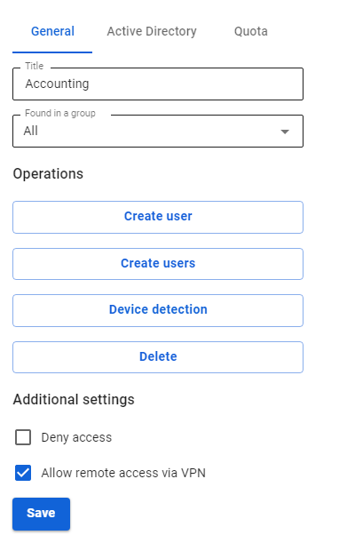
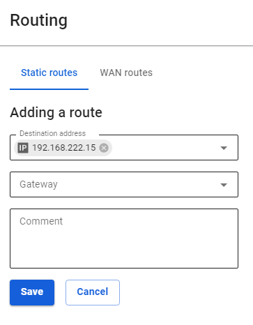
3. Add routes to the routing table. To do this, go to Services -> Routing -> Static routes and click the add button. We need to add the following route:
- Destination address:
192.168.1.0/255.255.255.0 - Gateway: user "office2"

Configuring the router in office No2
In the example, the settings are given for SafeUTM acting as a router. As a rule, routers from different manufacturers are configured similarly.
You need to create a VPN connection to a remote server and register a route to a remote network via a VPN connection. To do this, follow these steps:
- Create a new interface of the type Ethernet + PPTP. As a VPN server, specify the external IP address or domain name of office No1 and use the data of the account created on the server in office No1 (in our example, office2) as a username and password.
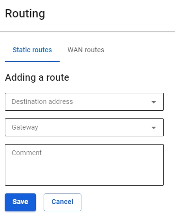
- Add routes to the routing table. To do this, in the web interface go to the section Services -> Routing and click the add button. Specify the required values and click Save. We need to add the following route:
Destination address:192.168.0.0/24Gateway: Select the Ethernet + PPTP interface that you have created.
Incoming Connection of Cisco IOS to SafeUTM via IPsec
Following the steps in this article, you can combine Cisco and SafeUTM networks via IPsec using PSK.
Find below the connection setup according to the scheme shown in the figure: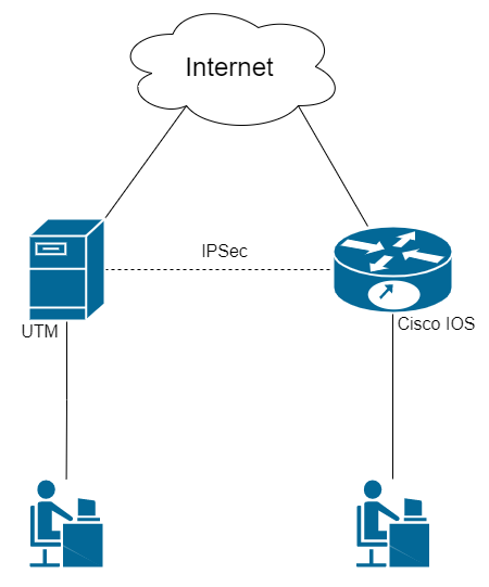
Step 1. Initial Setup of SafeUTM
Configure the local and external interfaces on SafeUTM. Detailed information can be found in the article Initial setup.
Step 2. Initial setup of Cisco IOS EX
Cisco configuration can be done through the device console (the configuration is described below)
1. Setting up the local interface:
enable
conf t
interface GigabitEthernet2
ip address {local IP Cisco} {subnet mask}
no shutdown
ip nat inside
exit
2. Configuring the external interface:
interface GigabitEthernet1
ip address {Cisco external IP} {subnet mask}
no shutdown
ip nat outside
exit
3. Check if there is a connection between the external interfaces of SafeUTM and Cisco. To do this, use the ping {external IP UTM} command in the Cisco console. The result of the command output is the presence of ICMP responses.
4. Creating an access list with local network addressing:
ip access-list extended NAT
permit ip {Cisco local subnet} {reverse subnet mask} any
exit
5. Configuring NAT (for more information on configuring this item, you can read the article on the official Cisco website):
ip nat inside source list NAT interface GigabitEthernet1 overload
exit
6. Saving configuration settings:
write memory7. Having saved the settings, make sure that there is Internet access from the Cisco LAN. To do this, visit any website (for example: https://www.cisco.com) from a device on the Cisco LAN.
Step 3. Configuring IKEv2+IPsec on Cisco
1. Creating a proposal (you can read detailed information on setting up this item in the article on the official Cisco website):
conf t
crypto ikev2 proposal ikev2proposal
encryption aes-cbc-256
integrity sha256
group 19
exit
2. Creating a policy (you can read detailed information on setting up this item in the article on the official Cisco website):
crypto ikev2 policy ikev2policy
match fvrf any
proposal ikev2proposal
exit
3. Creating a peer (key_id is the ID of the remote party, i.e. SafeUTM). Detailed information on setting up this item can be found in the article on the official Cisco website.
crypto ikev2 keyring key
peer strongswan
address {UTM external IP}
identity key-id {key_id}
pre-shared-key local {psk}
pre-shared-key remote {psk}
exit
exit
4. Creating an IKEv2 profile (you can read detailed information on configuring this item in the article on the official Cisco website):
crypto ikev2 profile ikev2profile
match identity remote address {UTM external IP} 255.255.255.255
authentication remote pre-share
authentication local pre-share
keyring local key
exit
5. Setting up encryption in esp:
crypto ipsec transform-set TS esp-gcm 256
mode tunnel
exit
6. Creating ipsec-isakmp:
crypto map cmap 10 ipsec-isakmp
set peer {UTM external IP}
set transform-set TS
set ikev2-profile ikev2profile
match address cryptoacl
exit
7. Configuring the crypto map on the external interface:
interface GigabitEthernet1
crypto map cmap
exit
8. Creating an access list for traffic between Cisco and UTM local networks:
ip access-list extended cryptoacl
permit ip {Cisco local subnet} {reverse subnet mask} {UTM local subnet} {reverse subnet mask}
exit
9. Adding traffic exceptions between Cisco and UTM local networks to the NAT access list (the deny rule should be higher than permit):
ip access-list extended NAT
no permit ip {Cisco local subnet} {reverse subnet mask} any
deny ip {Cisco local subnet} {reverse subnet mask} {local UTM subnet} {reverse subnet mask}
permit ip {Cisco local subnet} {reverse subnet mask} any
exit
end
10. Saving configuration settings:
write memoryStep 4. Creating an incoming IPsec connection on UTM
1. In the SafeUTM web interface, open tab Services -> IPsec -> Devices.
2. Add a new connection:
- Connection name – any.
- Type – incoming.
- Authorization type – PSK.
- PSK – specify the PSK key that you entered in Step 3 item 3.
- Remote side identifier – insert the Cisco ID (Key ID parameter in Step 3 item 3).
- Home local network – specify the SafeUTM local area network.
- Remote local networks – specify the Cisco local network.
3. Save the created connection, then click on Turn on
4. Check that the connection is established (your connection will appear in the list of connections, in column Statuses the word Installed will be highlighted in green).
5. Check for traffic between local networks (TCP and web).
The final configuration of Cisco IOS
The final configuration of IKEv2 IPsec on Cisco IOS should look like this:
crypto ikev2 proposal ikev2proposal
 encryption aes-cbc-256
 integrity sha256
 group 19

crypto ikev2 policy ikev2policy
 match fvrf any
 proposal ikev2proposal

crypto ikev2 keyring key
 peer strongswan
  address 5.5.5.5
  pre-shared-key local QWEqwe1234567890
  pre-shared-key remote QWEqwe1234567890

crypto ikev2 profile ikev2profile
 match identity remote key-id key-id
 authentication remote pre-share
 authentication local pre-share
 keyring local key

crypto ipsec transform-set TS esp-gcm 256
 mode tunnel

crypto map cmap 10 ipsec-isakmp
 set peer 5.5.5.5
 set transform-set TS
 set ikev2-profile ikev2profile
 match address cryptoacl

interface GigabitEthernet1
! external interface
 ip address 1.1.1.1 255.255.255.0
 ip nat outside
 negotiation auto
 no mop enabled
 no mop sysid
 crypto map cmap

interface GigabitEthernet2
! local interface
 ip address 2.2.2.2 255.255.255.0
 ip nat inside
 negotiation auto
 no mop enabled
 no mop sysid

ip nat inside source list NAT interface GigabitEthernet1 overload

ip access-list extended NAT
 deny   ip 2.2.2.0 0.0.0.255 3.3.3.0 0.0.0.255
 permit ip 2.2.2.0 0.0.0.255 any
ip access-list extended cryptoacl
 permit ip 2.2.2.0 0.0.0.255 3.3.3.0 0.0.0.255
Outgoing SafeUTM Connection to Cisco IOS via IPsec
Following the steps in this article, you can combine Cisco and SafeUTM networks via IPsec using PSK.
Find below the connection setup according to the scheme shown in the figure: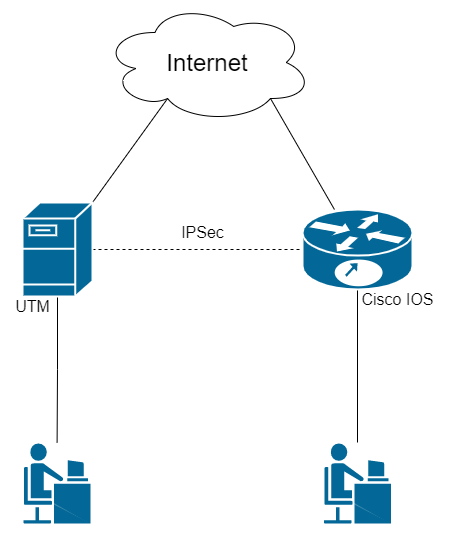
Step 1. Initial Setup of SafeUTM
Configure the local and external interfaces on SafeUTM. Detailed information can be found in the article Initial setup.
Step 2. Initial Setup of Cisco IOS EX
Cisco configuration can be done through the device console (the configuration is described below).
1. Setting up the local interface:
enable
conf t
interface GigabitEthernet2
ip address {Cisco local IP} {subnet mask}
no shutdown
ip nat inside
exit
2. Configuring the external interface:
interface GigabitEthernet1
ip address {Cisco external IP} {subnet mask}
no shutdown
ip nat outside
exit
3. Check if there is a connection between the external interfaces of SafeUTM and Cisco. To do this, use the ping {external IP UTM} command in the Cisco console. The result of the command output is the presence of ICMP responses.
4. Creating an access list with local network addressing:
ip access-list extended NAT
permit ip {Cisco local subnet} {reverse subnet mask} any
exit
5. Configuring NAT (for more information on configuring this item, you can read the article on the official Cisco website):
ip nat inside source list NAT interface GigabitEthernet1 overload
exit
6. Saving configuration settings:
write memory7. Having saved the settings, make sure that there is Internet access from the Cisco LAN. To do this, visit any website (for example: https://www.cisco.com) from a device on the Cisco LAN.
Step 3. Configuring IKEv2+IPsec on Cisco
1. Creating a proposal (you can read detailed information on setting up this item in the article on the official Cisco website):
conf t
crypto ikev2 proposal ikev2proposal
encryption aes-cbc-256
integrity sha256
group 19
exit
2. Creating a policy (you can read detailed information on setting up this item in the article on the official Cisco website):
crypto ikev2 policy ikev2policy
match fvrf any
proposal ikev2proposal
exit
3. Creating a peer (key_id is the ID of the remote party, i.e. SafeUTM). Detailed information on setting up this item can be found in the article on the official Cisco website.
crypto ikev2 keyring key
peer strongswan
address {UTM external IP}
identity key-id {key_id}
pre-shared-key local {psk}
pre-shared-key remote {psk}
exit
exit
4. Creating an IKEv2 profile (you can read detailed information on configuring this item in the article on the official Cisco website):
crypto ikev2 profile ikev2profile
match identity remote address {UTM external IP} 255.255.255.255
authentication remote pre-share
authentication local pre-share
keyring local key
exit
5. Setting up encryption in esp:
crypto ipsec transform-set TS esp-gcm 256
mode tunnel
exit
6. Creating ipsec-isakmp:
crypto map cmap 10 ipsec-isakmp
set peer {UTM external IP}
set transform-set TS
set ikev2-profile ikev2profile
match address cryptoacl
exit
7. Configuring the crypto map on the external interface:
interface GigabitEthernet1
crypto map cmap
exit
8. Creating an access list for traffic between Cisco and UTM local networks:
ip access-list extended cryptoacl
permit ip {Cisco local subnet} {reverse subnet mask} {UTM local subnet} {reverse subnet mask}
exit
9. Adding traffic exceptions between Cisco and UTM local networks to the NAT access list (the deny rule should be higher than permit):
ip access-list extended NAT
no permit ip {Cisco local subnet} {reverse subnet mask} any
deny ip {Cisco local subnet} {reverse subnet mask} {local UTM subnet} {reverse subnet mask}
permit ip {Cisco local subnet} {reverse subnet mask} any
exit

end
10. Saving configuration settings:
write memoryStep 4. Creating an outgoing IPsec connection on SafeUTM
1. In the SafeUTM web interface, open tab Services -> IPsec -> Devices.
2. Add a new connection:
- Connection name – any.
- Type – Outgoing.
- Authorization type – PSK.
- PSK – a random PSK key will be generated. You will need it to set up a connection in Cisco (see Step 3 item 3).
- UTM identifier – The key you entered will be used to identify the outgoing connection. Also, enter this ID in Cisco (see Step 3 item 3).
- Home local network – specify the SafeUTM local area network.
- Remote local networks – specify the Cisco local network.
3. Check that the connection has been established (your connection will appear in the list of connections, in the column Statuses the word Installed will be highlighted in green).
4. Check for traffic between local networks (TCP and web).
Final Configuration of Cisco IOS
The final configuration of IKEv2 IPsec on Cisco IOS should look like this:
crypto ikev2 proposal ikev2proposal
 encryption aes-cbc-256
 integrity sha256
 group 19

crypto ikev2 policy ikev2policy
 match fvrf any
 proposal ikev2proposal

crypto ikev2 keyring key
 peer strongswan
  address 5.5.5.5
  pre-shared-key local QWEqwe1234567890
  pre-shared-key remote QWEqwe1234567890

crypto ikev2 profile ikev2profile
 match identity remote key-id key-id
 authentication remote pre-share
 authentication local pre-share
 keyring local key

crypto ipsec transform-set TS esp-gcm 256
 mode tunnel

crypto map cmap 10 ipsec-isakmp
 set peer 5.5.5.5
 set transform-set TS
 set ikev2-profile ikev2profile
 match address cryptoacl

interface GigabitEthernet1
! external interface
 ip address 1.1.1.1 255.255.255.0
 ip nat outside
 negotiation auto
 no mop enabled
 no mop sysid
 crypto map cmap

interface GigabitEthernet2
! local interface
 ip address 2.2.2.2 255.255.255.0
 ip nat inside
 negotiation auto
 no mop enabled
 no mop sysid

ip nat inside source list NAT interface GigabitEthernet1 overload

ip access-list extended NAT
 deny   ip 2.2.2.0 0.0.0.255 3.3.3.0 0.0.0.255
 permit ip 2.2.2.0 0.0.0.255 any
ip access-list extended cryptoacl
 permit ip 2.2.2.0 0.0.0.255 3.3.3.0 0.0.0.255
Incoming pfSense connection to SafeUTM via IPsec
Following the steps in this article, you can combine pfSense and SafeUTM networks via IPsec using PSK.
The combined LANs should not overlap!
Setting up SafeUTM
1. In the SafeUTM web interface, open tab Services -> IPsec -> Devices.
2. Add a new connection:
- Connection name – any.
- Type – incoming.
- Authorization type – PSK.
- PSK – specify the PSK key to be used for the connection.
- Remote side identifier – any.
- Home local network – Specify the SafeUTM local area network that will be visible from the pfSense subnet.
- Remote local networks – Specify the pfSense local network that will be visible from the SafeUTM subnet.
3. Save the created connection, then click on the "Enable" button.
4. Two configuration files will be generated on SafeUTM in the /etc/strongswan/autogen/ folder. You need to go to the console and open the file of the type device_<number>.peer for editing.
5. From this file, you need to copy the value of the rightid line (approximate type –@#746573745f70736b). In the future, this value will need to be registered on pfSense.
6. The setup is complete, now let’s set up pfSense.
Setting up pfSense
1. In the pfSense web interface, go to tab VPN -> IPsec –> Tunnels.
2. Add a new connection:
- Key Exchange version – IKEv2.
- Internet Protocol – IPv4.
- Interface – Select the pfSense external interface that will be used to connect to SafeUTM.
- Remote Gateway – IP of the SafeUTM external interface.
- Description – any.
- Authentication Method – Mutual PSK.
- My identifier and Peer identifier – insert the value of the rightid line on SafeUTM here (see step 5 in setting up SafeUTM).
- Pre-Shared Key – insert the PSK key that was previously registered on SafeUTM.
- Encryption Algorithm: For SafeUTM version 13.0 and later, use the following parameters: Algorithm - AES256-GCM; Key length - 128 bit; Hash - SHA256; DH Group - Elliptic Curve 25519- 256.
All other values can be left by default.
3. Save the connection.
4. Click on the button Show Phase 2 Entries and add a new Phase 2. Specify here:
- Encryption Algorithm: For SafeUTM version 13.0 and later, use the following parameters: Algorithm - AES256-GCM; Key length - 128 bit; Hash - SHA256; DH Group - Elliptic Curve 25519- 256.
- Local Network – pfSense LAN which will be accessible from the SafeUTM subnet.
- Remote Network – SafeUTM LAN, which will be accessible from the pfSense subnet.
All other values can be left by default.
5. Save the connection.
6. Then you need to allow traffic to flow between the pfSense and SafeUTM local networks in the pfSense firewall (go to tab Firewall -> Rules -> IPsec and create two rules that allow traffic to flow between the SafeUTM and pfSense local networks).
Also, pay attention to the WAN firewall section – by default, incoming traffic from "gray" subnets is prohibited in it, so you need to remove this restriction.
7. Now go to tab Status -> IPsec (the created connection should appear there), and click on the Connect VPN button.
The setup is complete, the connection should be successfully established.
If the connection could not be established, and the pfSense firewall settings were made correctly, you should recreate the connection on UTM by specifying in the Key ID field the value that was specified in My identifier and Peer identifier for pfSense and try to connect again. No changes are required on the pfSense side.
Outgoing pfSense Connection to SafeUTM via IPsec
Setting up SafeUTM
1. In the SafeUTM web interface, open tab Services -> IPsec -> Devices.
2. Add a new connection:
- Connection name – any.
- Type – outgoing.
- Authentication type – PSK.
- PSK – specify the PSK key to be used for the connection.
- UTM identifier – any.
- Home local network – specify the SafeUTM local area network that will be visible from pfSense subnets.
- Remote local networks – specify the pfSense local network that will be visible from the SafeUTM subnet.
Setting up pfSense
1. In the pfSense web interface, go to tab VPN > IPsec > Advanced Options, and in the Child SA Start Action field select option None (Responder Only).
2. Add a new connection:
- Key Exchange version – IKEv2.
- Internet Protocol – IPv4.
- Interface – Select the pfSense external interface that will be used to connect to SafeUTM.
- Remote Gateway – IP of external interface SafeUTM.
- Description - any.
- Authentication Method – Mutual PSK.
- My identifier - My IP address.
- Peer identifier - KeyID tag. Enter the ID of the remote party, i.e. SafeUTM.
- Pre-Shared Key – enter the PSK key.
- Encryption Algorithm:
Algorithm - AES256-GCM;
Key length - 128 bit;
Hash - SHA256;
DH Group - Elliptic Curve 25519-256.
3. Save the connection.
4. Click the button Show Phase 2 Entries and add a new Phase 2 and enter the following values:
- Encryption Algorithm:
Algorithm - AES256- GCM; Key length - 128 bit; Hash - SHA256; DH Group - Elliptic Curve 25519-256. - Local Network – pfSense LAN which will be accessible from the SafeUTM subnet.
- Remote Network – SafeUTM LAN, which will be accessible from the pfSense subnet.
All other values can be left by default.
5. Save the connection.
6. Then you need to allow traffic to flow between the pfSense and SafeUTM local networks in the pfSense firewall (go to tab Firewall -> Rules -> IPsec and create two rules that allow traffic to flow between the SafeUTM and pfSense local networks).
7. Also pay attention to the WAN firewall section – by default, incoming traffic from "gray" subnets is prohibited in it, so you need to remove this restriction.
8. Now go to tab Status -> IPsec (the connection that was created should appear there), and click on the Connect VPN button.
The setup is complete, the connection should be successfully established.
If the connection could not be established, and the pfSense firewall settings are correct, you should recreate the connection to UTM by specifying in the field Key ID the value specified in My identifier and Peer identifier of pfSense, and try to connect again. On the pfSense side, no changes are necessary.
Connecting Keenetic via SSTP
You can connect routers with SSTP protocol support in site-to-site VPN mode.
If you do not need access from the central office to the network for Keenetic, then use the article Connecting Wi-Fi Keenetic Routers via SSTP on client-to-site connection.
Setting up SafeUTM
1. Enable and configure the port and domain for SSTP in Users -> VPN connections.
2. In Users -> User & Group create a special user for the remote router. Check the box Allow remote access via VPN. The username/password of the user will be used on the router, save or write them down.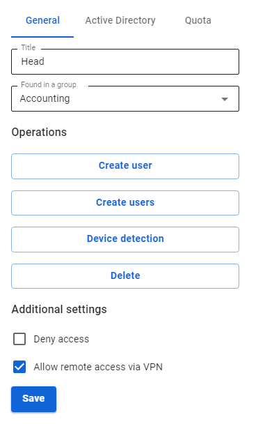
3. Register the routes to the remote network. For example, if the network behind the router is 192.168.10.0/24, you need to add the following route to the section Services -> Routing -> Static routes: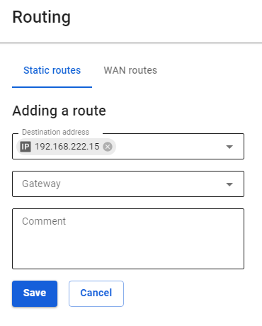
Configuring Keenetic Router
Configure the VPN connection of the Keenetic router according to the instructions for client-to-site connections.
Do not forget to follow all three steps:
- Set up a VPN connection.
- Set up routes.
- Configure DNS to resolve the local domain (if using Active Directory).
Verification and Possible Problems
To check the connection, use the ping and traceroute utilities.
If a VPN connection is established, but there is no access to the resources of one local network from another, use the instructions from the article to diagnose possible problems.
Most often, access is blocked in Windows due to network profile settings.
You can allow access to "non-local" networks in all profiles, by running the command in PowerShell (launched with elevated administrator rights): Enable-NetFirewallRule -Group "@FirewallAPI.dll,-28502"
Connecting Kerio Control to SafeUTM via IPsec
Following the steps of the article below, you can combine Kerio Control and SafeUTM networks via IPsec using PSK.
The combined LANs should not overlap!
Setting up SafeUTM
1. In the SafeUTM web interface, open tab Services -> IPsec -> Devices.
2. Add a new connection and fill in the following fields:
- Connection name – specify an arbitrary name for the connection. Maximum 42 characters.
- Type – select Incoming.
- Authentication type – select the PSK type.
- PSK – specify the PSK key to be used for the connection.
- Remote side identifier – specify the key that will be used to identify the connection on Kerio.
- Home local network – Select the SafeUTM LAN that will be visible from the Kerio Control subnet.
- Remote local networks - specify the Kerio Control LAN that will be visible from the SafeUTM subnet.
3. Save the created connection, then activate the connection by clicking on the Enable icon in the column Operations.
4. The setup is complete, Kerio Control needs to be configured.
Configuring Kerio Control
1. By default, Kerio Control uses IKEv1 to create connections to third-party devices. You can enable IKEv2 via the console. To do this, follow these steps:
1.1. Connect to Kerio Control via SSH.
1.2. Go to the folder /var/winroute
1.3. Open winroute.cfg file for editing.
1.4. In it, find the section starting with the text <table name="Firewall">
1.5. In this section, find the line <variable name="IKEVersion">ikev1</variable> and change ikev1 in it to ikev2
1.6. After that, it is advisable to restart the server and make sure that the changes in the settings are saved.
2. In the section Traffic rules, allow VPN services traffic.
3. Then go to the section Interfaces and click Add. In the drop-down list, select VPN tunnel...
4. The connection creation window will open. In it, select:
- Type – IPsec.
- The name is arbitrary.
- Activate Enable this tunnel.
- Select type Active and in the field below it, enter the IP address of the SafeUTM external interface that will be used for the connection.
- Select the Predefined key and enter the PSK key that will be used to connect.
- Local ID - specify the key that was set in the Remote side identifier field (p. 2);
- Remote ID - specify the IP address of the SafeUTM external interface;
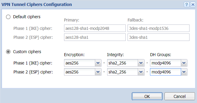
- Under setting the ciphers, click on Edit. Set ciphers as in the screenshot:

An example of the final settings is shown in the screenshot below.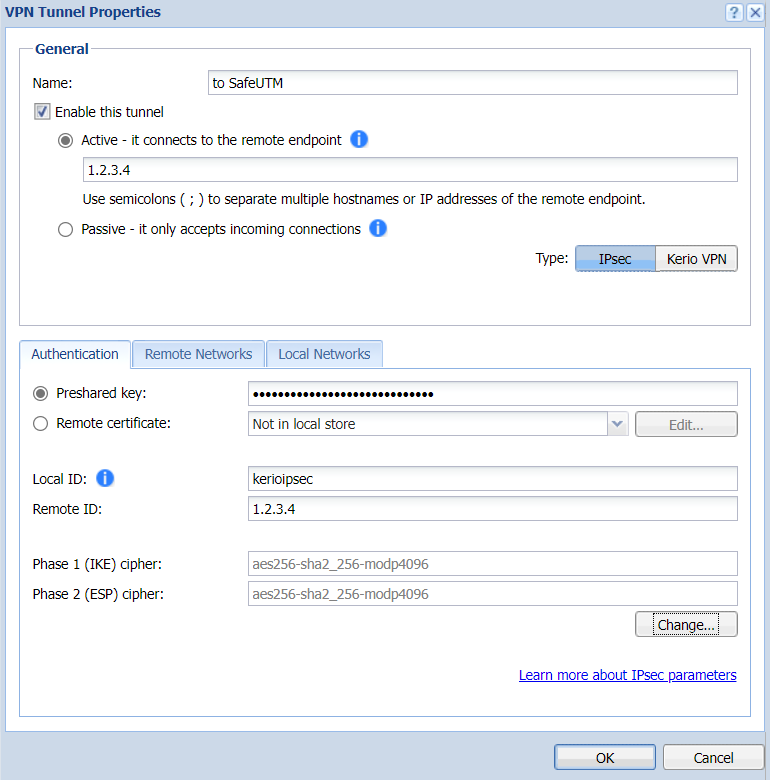
5. Go to the section Remote networks, click Add and enter the information about SafeUTM local network, which will be visible from the Kerio Control subnet.
6. Then in the section Local networks either click on the button Use automatically defined local networks, or configure networks that will be visible from the SafeUTM subnet manually, as in the previous step.
7. Setup is complete. After adding a new interface, you need to click Apply. After that, the connection should be successfully established, and the information about this is displayed in the table in the Interfaces section.
In case of problems, first of all, pay attention to Kerio Control firewall settings.
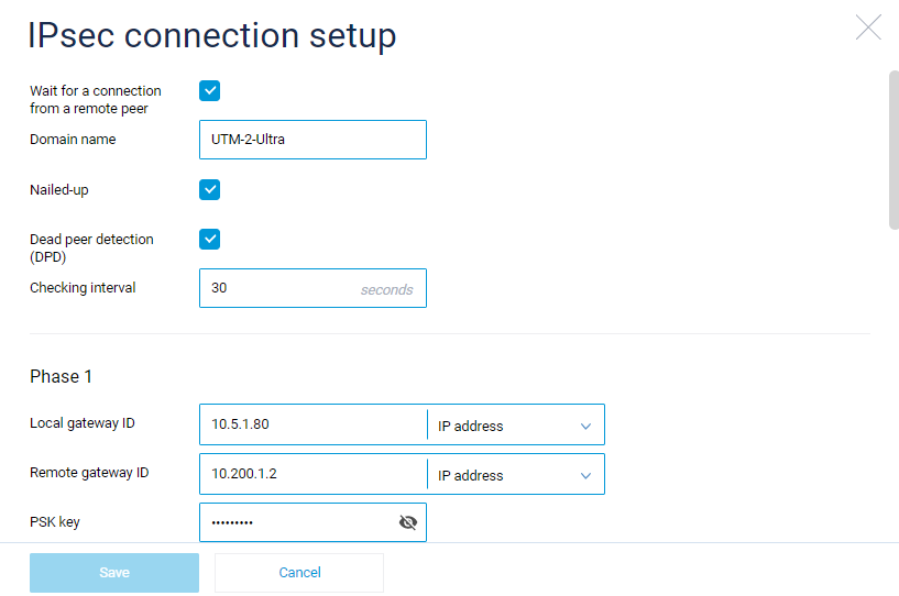
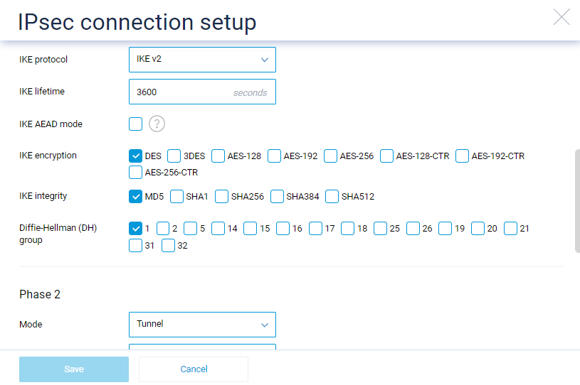
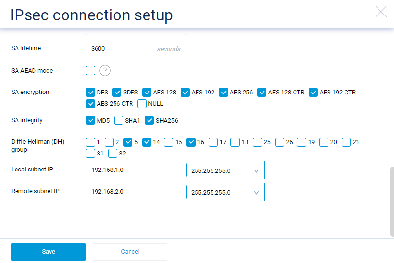
Connecting Keenetic via IPsec
On the SafeUTM side, configure the connection settings in the Services -> IPSec -> Devices section.
On the Keenetic device side, use the following encryption protocol settings: