4.5. Setup - Services
- Network Interfaces
- Network Interfaces
- Configuring Local Ethernet
- Configuring External Ethernet
- Configuring PPTP Connection
- Configuring L2TP Connection
- Configuring PPPoE Connection
- Connection via 3G and 4G
- Channel Aggregation & Failover
- Routing
- BGP
- OSPF
- Proxy
- Proxy
- Configuring Proxy with Single Interface
- Exclude IP Addresses from Proxy Server Processing
- Connecting to External ICAP Services
- Reverse Proxy
- DNS
- DHCP Server
- IPSec
- Connecting offices (site-to-site)
- PPTP VPN
- Incoming Connection of Cisco IOS to SafeUTM via IPsec
- Outgoing SafeUTM Connection to Cisco IOS via IPsec
- Incoming pfSense connection to SafeUTM via IPsec
- Outgoing pfSense Connection to SafeUTM via IPsec
- Connecting Keenetic via SSTP
- Connecting Kerio Control to SafeUTM via IPsec
- Connecting Keenetic via IPsec
- Certificates
Network Interfaces
Network Interfaces
A detailed description of creating and configuring each type of network interface is described in the following instructions:
All created interfaces are presented in the form of a table:
In the edit mode, it becomes possible to change the name, network card (by clicking the pencil button), and configuration settings (manually or automatically):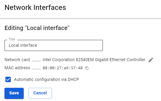
If the Network card is already in use by any interface, then UTM will display an error window "NIC/VLAN tag combinations must be unique".
When migrating UTM from one physical machine to another (disk transfer or backup restore on new hardware), the settings of all network interfaces specified before the migration will be restored. Use the trash bin button to remove unnecessary interfaces.
Example: the original version of UTM 13.X -> migrated UTM to new hardware -> configured new hardware -> upgraded -> in the Network interfaces section, old (before migration) and new (after migration and configuration) network interfaces will be displayed.
Configuring Local Ethernet
Manual and automatic configuration using the DHCP protocol.
Be careful!
If you select Local Ethernet and set it as External Ethernet, you will not be able to access the Internet.
Manual Configuration
To configure the connection in the web interface, follow these steps:
1. Go to the menu Services -> Network Interfaces.
2. Click on the icon (+) in the upper right corner of the window and select Local Ethernet.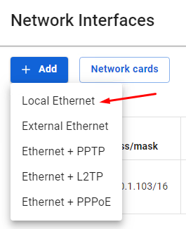
3. Select a network card.
4. Fill in the fields listed below:
- Title - The name you will use to identify the interface in the future. Maximum 42 characters.
- Network card - The network adapter that will be used to connect.
- VLAN tag - VLAN ID. Such network interface is considered a VLAN interface. Also, one Ethernet interface can be created without specifying VLAN belonging to this network segment that will receive untagged traffic. Regular Ethernet interfaces, without specifying the VLAN ID, are created on the physical interface only in a single copy. The field is filled in only if the network card is already in use.
- Automatic configuration via DHCP - It is used if your Internet provider supports the ability to automatically configure the Ethernet interface using the DHCP protocol.
- IP address/mask - You can assign multiple IP addresses to the interface. At least one IP address must be specified.
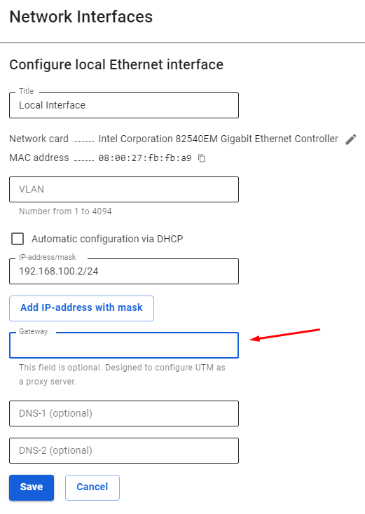
- Gateway - Gateway IP address.
- DNS - Two fields are available to specify the DNS server (optional).
The Gateway field in the Local interface is set only if:
- There is no External UTM interface;
- UTM is only used as a proxy.
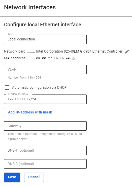
Configuration example:

Automatic Configuration
It is used if your Internet provider supports the ability to automatically configure the Ethernet interface using the DHCP protocol.
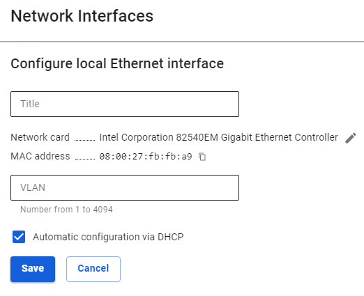
Configuration example:

Configuring External Ethernet
Manual and automatic configuration using the DHCP protocol.
Usually, all necessary information for configuration is contained in the contract with your Internet provider.
Manual Configuration
To configure the connection in the web interface, follow these steps:
1. Go to the menu Services -> Network Interfaces.
2. Click on the icon (+) in the upper right corner of the window and select External Ethernet.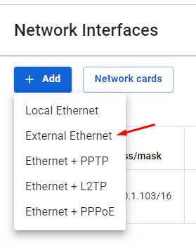
3. Select a network card.
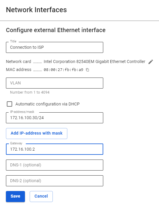
4. Fill in the fields listed below:
- Title - The name you will use to identify the interface in the future. Maximum 42 characters.
- Network card - The network adapter that will be used to connect.
- VLAN tag - VLAN ID. Such network interface is considered a VLAN interface. Also, one Ethernet interface can be created without specifying VLAN belonging to this network segment that will receive untagged traffic. Regular Ethernet interfaces, without specifying the VLAN ID, are created on the physical interface only in a single copy. The field is filled in only if the network card is already in use.
- Automatic configuration via DHCP - It is used if your Internet provider supports the ability to automatically configure the Ethernet interface using the DHCP protocol.
- IP address/mask - You can assign multiple IP addresses to the interface. At least one IP address must be specified.
- Gateway - Gateway IP address.
- DNS - Two fields are available to specify the DNS server (optional).
Configuration example:

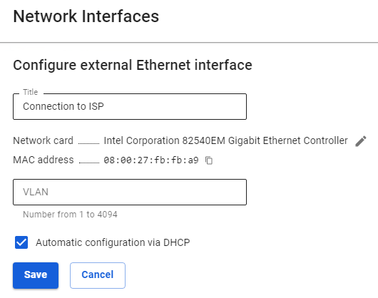
Automatic Configuration
It is used if your Internet provider supports the ability to automatically configure the Ethernet interface using the DHCP protocol.
Configuration example:

Configuring PPTP Connection
Connection via PPTP protocol is used by Internet service providers in order to provide a more reliable authorization.
To configure such a connection in the web interface, follow these steps:
|
Parameter |
Description |
|
Title |
The name you will use to identify the interface in the future. Maximum 42 characters. |
|
Network card |
The network adapter will be used to connect to the Internet provider. |
|
VLAN tag |
The VLAN ID in which UTM will be present. Such network interface is considered a VLAN interface. Fill only in the case a network card is already in use. |
|
Automatic configuration via DHCP |
Used if your Internet provider supports the ability to automatically configure the Ethernet interface using the DHCP protocol. |
|
IP address/mask |
You can assign multiple IP addresses to the interface. At least one IP address must be specified. |
|
Gateway |
Gateway IP address. |
|
DNS |
There are two fields available to specify the DNS server. Optional fields. |
|
VPN Server |
IP address or domain name of the PPTP server. |
|
Login |
Username for the PPTP connection. |
|
Password |
Password for the PPTP connection. |
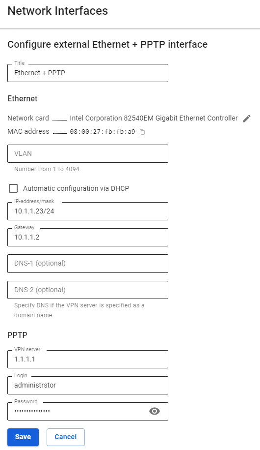
5. Make sure the entered values are correct and click Save.
Configuration example:

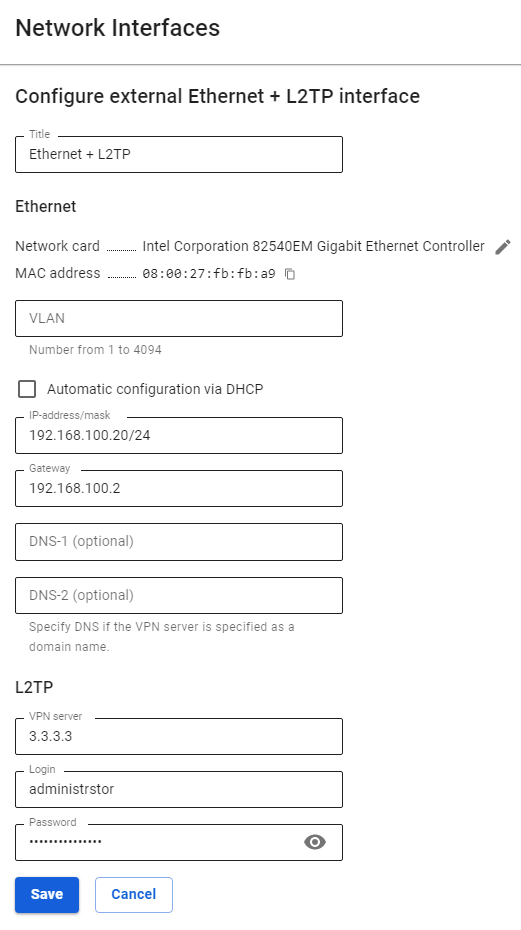
Configuring L2TP Connection
Connection via L2TP protocol is sometimes used by Internet service providers in order to provide more reliable authorization.
To configure such a connection in the web interface, follow these steps:
|
Parameter |
Description |
|
Title |
The name you will use to identify the interface in the future. Maximum 42 characters. |
|
Network Card |
The network adapter will be used to connect to the Internet provider. |
|
VLAN tag |
The VLAN ID in which UTM will be present Such network interface is considered a VLAN interface. Fill in only if the network card is already in use. |
|
Automatic configuration via DHCP |
Used if your Internet provider supports the ability to automatically configure the Ethernet interface using the DHCP protocol. |
|
IP address/mask |
You can assign multiple IP addresses to the interface. At least one IP address must be specified. |
|
Gateway |
Gateway IP address. |
|
DNS |
Two fields are available to specify the DNS server (optional). |
|
VPN Server |
IP address or domain name of the L2TP server. |
|
Username |
User name for the L2TP connection. |
|
Password |
Password for the L2TP connection. |
- Make sure that the entered values are correct and click Save.
Configuration example:

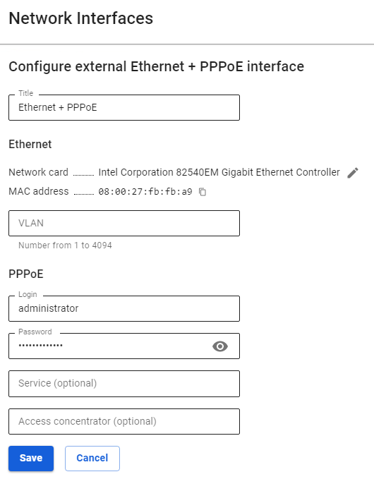
Configuring PPPoE Connection
Connection via PPPoE protocol is traditionally used by providers offering connection via xDSL.
To configure the connection in the web interface, follow these steps:
|
Parameter |
Description |
|
Title |
The name you will use to identify the interface in the future. Maximum 42 characters. |
|
Network card |
The network adapter will be used to connect to the Internet provider. |
|
VLAN tag |
The VLAN ID in which UTM will be present Such network interface is considered a VLAN interface. Fill in only if the network card is already in use. |
|
Login |
Username for PPPoE connection. |
|
Password |
Password for PPPoE connection. |
|
Service |
Service ID. If you don't know what to enter, leave the field empty. |
|
Access concentrator (Hub) |
Hub ID. If you don't know what to enter, leave the field empty. |
- Make sure the entered values are correct and click Save.
Configuration example:

Connection via 3G and 4G
To connect to the networks of mobile operators, it is possible to use 4G routers with Ethernet interfaces.
The server also supports some models of USB modems, for example, Huawei E8372. When connected, the USB modem will be displayed in SafeUTM as a new Ethernet interface.
Channel Aggregation & Failover
Configuring channel failover, static and dynamic aggregation.
If you have multiple connections to Internet service providers, you can use them in the following ways:
- Failover of one connection so that when it is disconnected, traffic goes through other available connections.
- Static aggregation of traffic between multiple connections. With it, some users of the local network will access the Internet through one provider, some through another.
- Dynamic aggregation of traffic between multiple connections. With it, connections will switch alternately depending on the load, and sessions from all users will be evenly distributed between them.
Preparation
Create an additional connection to the Internet provider. The process of creating connections is described in the article on External Ethernet connection. Thus, the server must have at least two Internet connections.
To work with traffic in SafeUTM, it is important to consider two things: routing and NAT. This applies to both aggregation and failover.
Channel Redundancy
To set up redundancy, go to Services -> Channel Aggregation & Failover and select the Failover mode.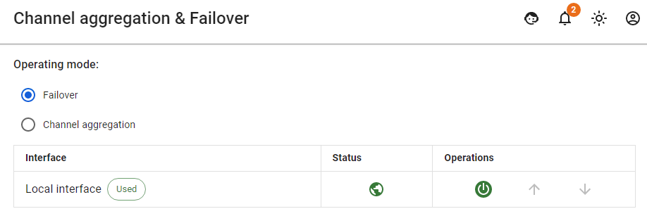
- The priority of using connections is set by their order in the table, from top to bottom. The connection that is currently in use is marked with the tag In use.
- To change the priority, you can use the corresponding controls (arrow icons).
- If the Internet has become unavailable through the connection used, the system will switch to a higher priority one that has access to the Internet.
Access to the Internet via Specific Connection to Provider (Static Aggregation)
Such scheme of connection to several Internet service providers is often used in the following cases:
- When some resources on the Internet are cheaper to visit through another Internet provider and traffic needs to be routed through it.
- When it is necessary to grant access to the internal networks of one of the providers to certain users or groups of users.
To configure this connection scheme, follow these steps:
Example of a rule:

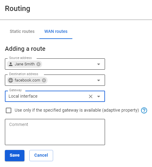
In this example, traffic directed to facebook.com from user Jane Smith will be directed through the connection to the provider's Local interface.
Load Aggregation Across Multiple Connections (Dynamic Aggregation)
To configure this connection scheme, follow these steps:
- Go to Services -> Channel Aggregation & Failover.
- Select the operating mode Channel Aggregation.

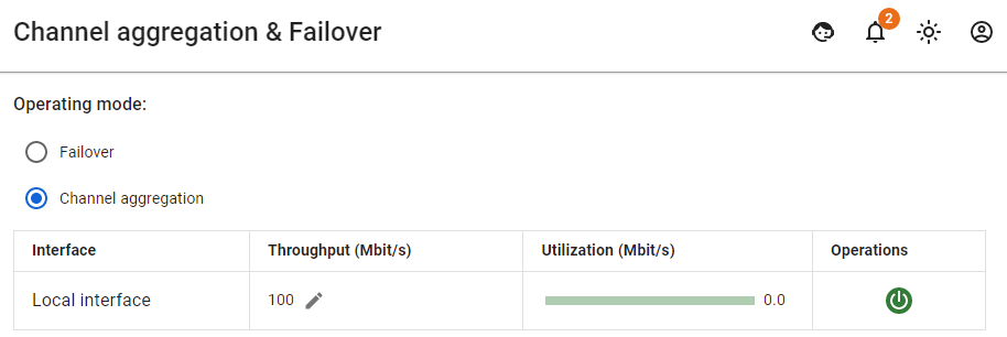
To evenly distribute sessions between connections, you must specify the value Bandwidth – the maximum Internet speed according to the tariffs of your providers. By default, the bandwidth is set to 100 Mbit/s. The server will automatically balance traffic depending on a load of connections.
You do not need to create routes or perform any other settings to balance traffic. Proxy server traffic will also be balanced automatically.
Routing
Used to redirect network traffic passing through SafeUTM.
It has a number of advantages over some other traditional routing systems. Among them are:
- The ability to specify the source network directly in the route.
- Adaptivity function (in case of gateway or interface unavailability, the route search will continue according to the following routing rules).
It is possible to route local and external networks in the SafeUTM web interface. You can create and edit routes via the SafeUTM web interface in the section Services -> Routing.
To organize access to remote networks via a router on a local network, read the article by following the link.
Routing of LANS
Local area network routing operates within the local area network and does not have a Source address field when adding a route. To add a new route, go to the Local area networks routing tab and click Add:
- Destination address – select the objects that this rule will apply to when accessing. Possible types of objects: IP address, subnet.
- Gateway – select the object through which the traffic will be routed. Possible types of objects: network interfaces, IP addresses.
- Comment – an optional field for describing the route. Maximum 128 characters.
Routing of External Networks
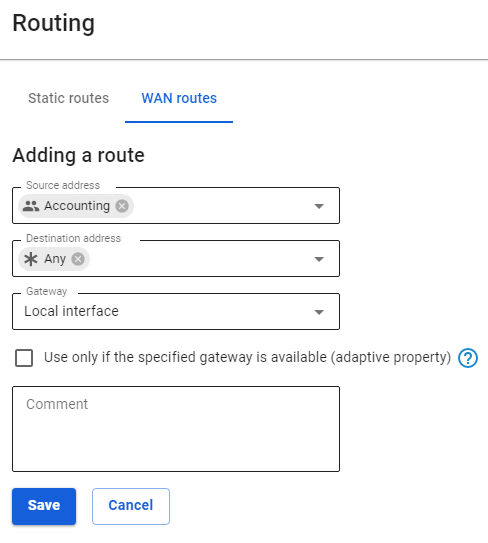
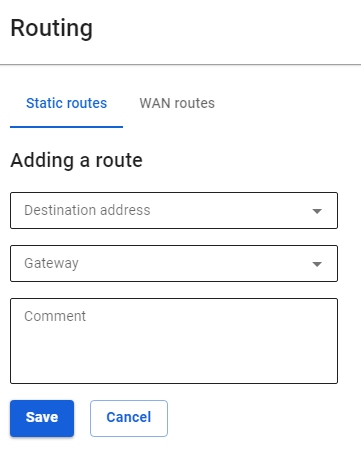
To add a new route, go to the routing tab of WAN routes and click Add. A route creation form will open on the page: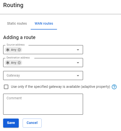
Description of each option:
- Source address – select the objects for which this rule will be applied. Possible types of objects: groups, users, IP address, domain, IP address range, subnet, and address list.
- Destination address – select the objects that this rule will apply to when accessing. Possible types of objects: groups, users, IP address, domain, IP address range, subnet, and address list.
- Gateway – select the object through which the traffic will be routed. Possible types of objects: network interfaces, IP addresses.
- Use only if the specified gateway is available (adaptive property) – if this property is enabled, then if the gateway or interface is unavailable, the route search will continue according to the following routing rules, and if the property is disabled (by default), traffic is sent to the selected gateway or interface. If the gateway is unavailable or the interface does not work, then such traffic will be dropped (destination unreachable).
- Comment – an optional field for describing the route. Maximum 128 characters.
After saving the route, the page looks like this: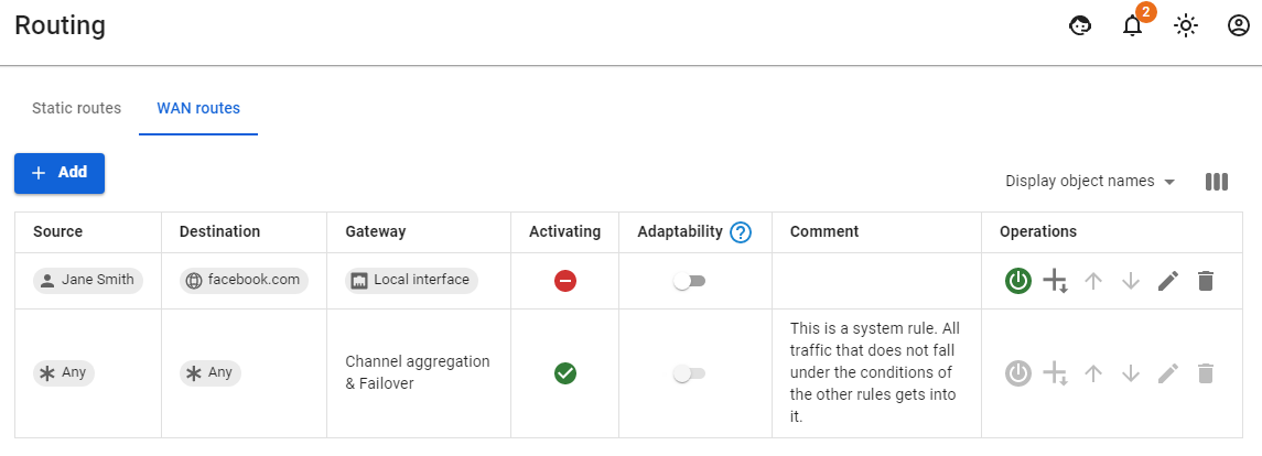 Arrow icons increase or decrease the priority of the rule execution.
There is a status Activating in the table. It has two states:
|
State |
Description |
|
|
The route is active, and traffic falling under the conditions of the route will be redirected to the specified Gateway. |
|
|
The route is not active, and traffic falling under the conditions of the route will not be this rule. |


Traffic that does not fall under the conditions of the routing rules, or with object Any as a gateway, will be sent to Channel Aggregation & Failover.
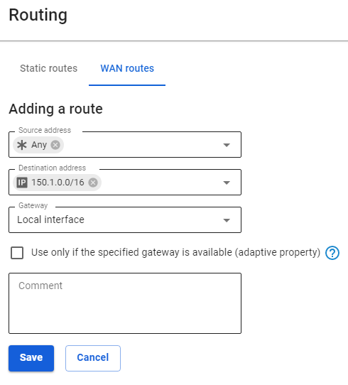
Examples of popular routes
When routing traffic through connections to the provider, it is important to understand that most often one route is not enough, you will also need to redefine the address using SNAT, otherwise, such a route simply will not work. SNAT can be configured using a firewall.
Task: any traffic to subnet 150.1.0.0/16 needs to be directed to the local gateway
Task: all user traffic from the group Accounting needs to be directed through the gateway of the selected network interface
If you are setting up a route to remote network access via an additional router located on the same LAN as the clients, make sure that you have avoided "asymmetric routing" and moved the router to the DMZ.
BGP
Configuring BGP to exchange information about the availability of networks.
SafeUTM 13 implements support for BGP (Border Gateway Protocol), which is the main dynamic routing protocol used on the Internet.
Setting up your autonomous system
1. Enter your AS number in the AS Number field and click Save: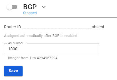
2. Move the switch of the BGP section to the enabled position;
3. SafeUTM will populate the Router ID field automatically if the BGP section switch is on.
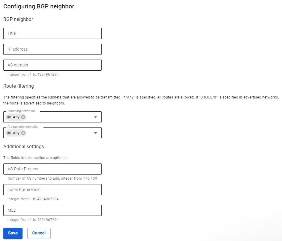
Configuring BGP neighbors
1. To add a BGP neighbor, click Add in the upper right corner;
2. Fill in the following fields:
- Title - any value;
- IP address - BGP neighbor IP address;
- AS number - Neighbor's BGP AS number;
- Incoming networks - a filter in which you need to select the network from which you want to receive information. If the Any object is selected, then filtering will be disabled and all networks from the BGP neighbor will be accepted. Preset filters object Default route matches filter 0.0.0.0/0;
- Announced networks - a filter in which you need to select the network about which you want to send information. If Any object is selected, then filtering will be disabled and information about all known UTM routes will be transmitted (redistribute static, connected, OSPF ). Preset filters object Default route matches filter 0.0.0.0/0;
- AS-Path Prepend - the higher the value, the less priority the channel becomes;
- Local Preference - determines the path priority for traffic to exit. The larger the value, the less priority the channel becomes;
- MED - determines the path priority for traffic ingress. The lower the value, the more priority the path.

For Incoming networks and Announced networks, the Any object cannot be set simultaneously with other filters.
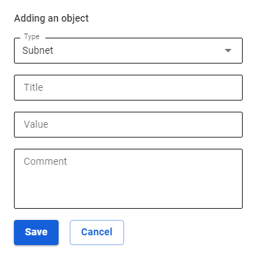
If there is no required object for filtering, then you can create it by selecting Create a new object in the Incoming networks or Announced networks field:
- Title - any value;
- Value - subnet value in the format: subnet/subnet mask, for example 192.168.100.0/24.

OSPF
SafeUTM 13 supports OSPF (Open Shortest Path First), a routing protocol based on the state of channels. A channel is a router interface or network segment that connects two routers. The state data of these channels is called the channel state.
The use of this module is best suited for networks that have network load balancing and channel redundancy.
An example of topology using OSPF is shown in the diagram below:
The principle of routing according to the state of the channel
1. Establishing adjacency relationships with neighboring devices
A router using OSPF sends greeting packets to identify all neighboring devices within these channels. If there is a neighboring device, the router tries to establish an adjacency relationship with it.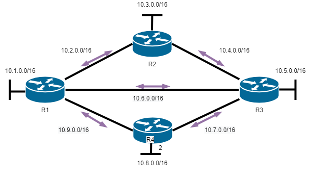
2. Exchanging channel state announcements
After the adjacency is established, the devices exchange channel state announcements (LSAs). LSAs contain information about the state and cost of each channel with a direct connection.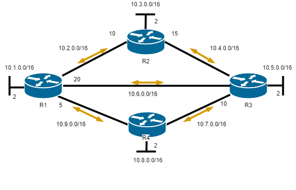
3. Creating a communication state database
Based on the LSA announcement, routers collect a database that contains data about the network topology in the area.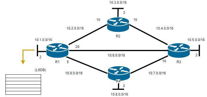
4. Executing the SPF algorithm
Then the SPF algorithm is executed on the devices, resulting in the creation of a tree of shortest paths.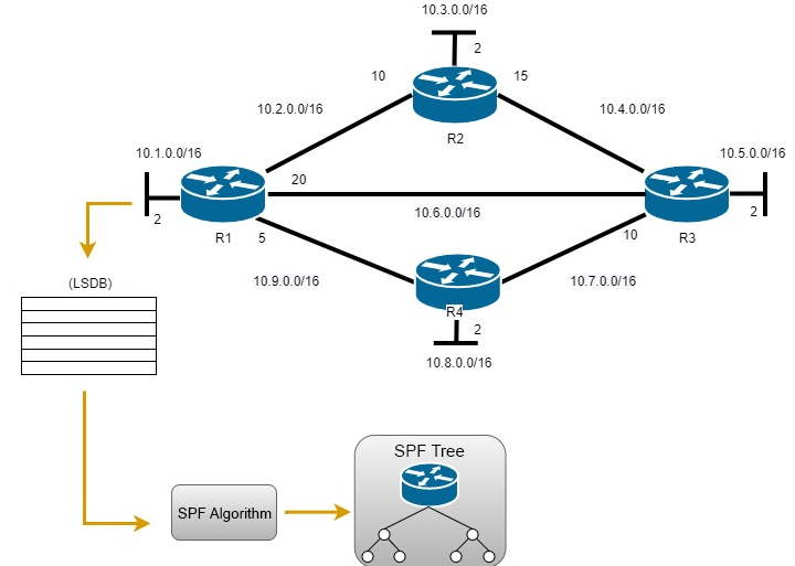
5. Choosing the best route
Based on the SPF tree data, the best paths for the IP routing table are proposed. A route is added to the routing table if there is no route source to the same network with a smaller administrative distance, for example, a static route. Routing decisions are made based on entries in the routing table.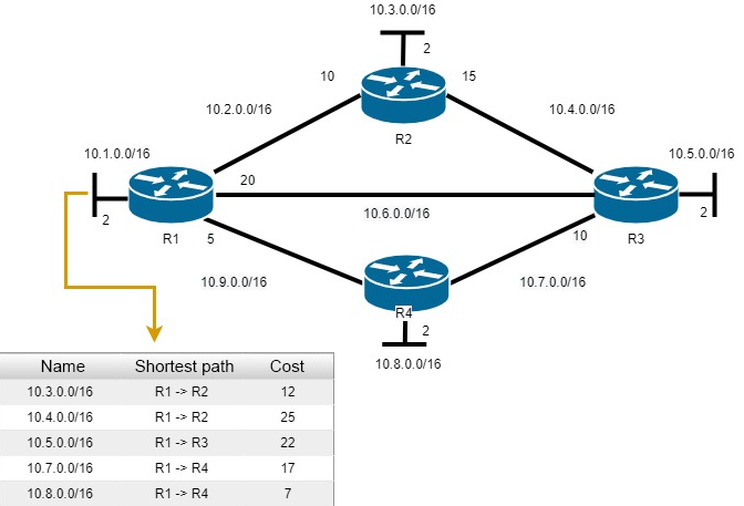
Setting up SafeUTM
To configure OSPF on UTM, follow these steps:
- In the UTM web interface, go to Services -> OSPF and click Add.
- Fill in the following fields:
- Interface - select the local interface connected to the router.
- Area ID - enter the zone number (for small networks, enter zone 0). The name of the zone can be entered as a number or IP address by clicking the icon A/B.
- Cost - enter the cost of the route. - Click Save.
Configuration example: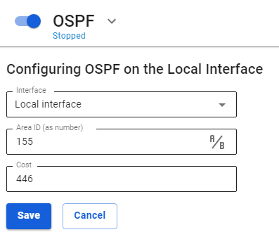
Example of a ready table: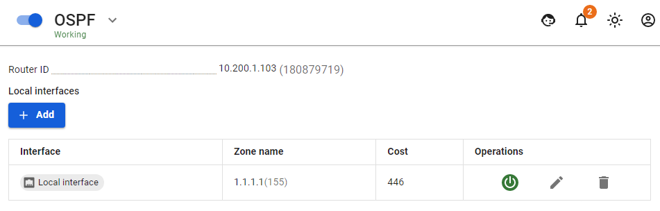
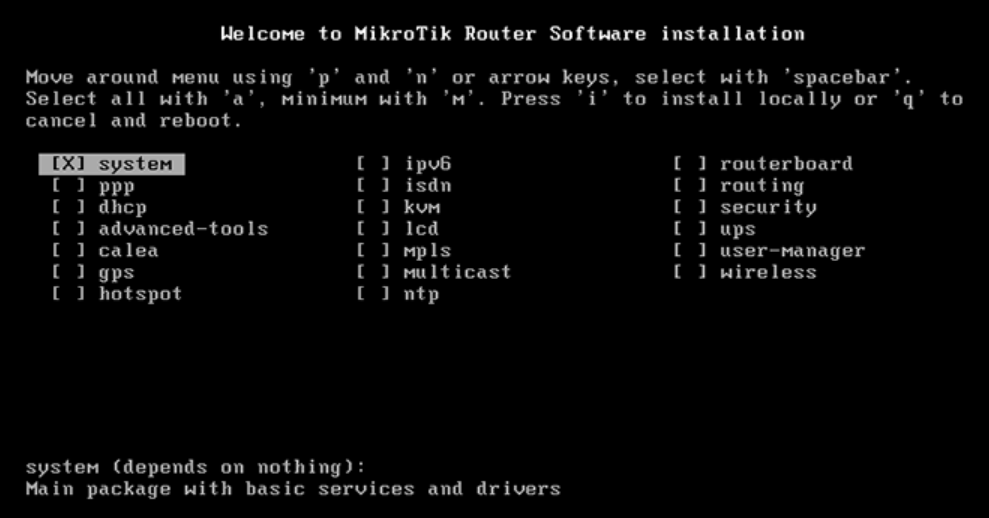
Setting up MikroTik
1. Install and boot up RouterOS:
- Select the Routing with X
- Specify the necessary interfaces but WITHOUT static routes.

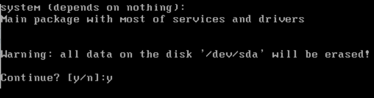
- To start the installation enter "i" and press Enter.
- You will see the warning "All data on the disk will be erased. Continue?". Enter y and press Enter:

2. After the RouterOS is installed, reboot the router by pressing Enter: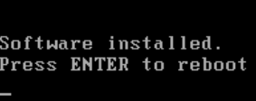
3. Default login is "admin", password is an empty field.
4. Set the admin login/password.
5. Run the following command: routing ospf area add area-id=х.х.х.х default-cost=1 disabled=no inject-summary-lsa=no name=area1 type=default where x.x.x.x - the name of the zone that was specified when setting up SafeUTM within the network;
6. To transfer any other networks to neighboring devices via dynamic routing, enter the following command: routing ospf network add network=(other subnets)/24 area=area1
7. Repeat the command from step 6 to add each subnet.
8. To display the routing table, enter the command: ip route print
Proxy
Proxy
Setting up a direct connection to the proxy server.
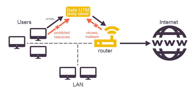
Proxy Server for Web Traffic
You do not need to explicitly specify the proxy settings on the LAN hosts. Specifying UTM as the default gateway for devices on the network is sufficient.
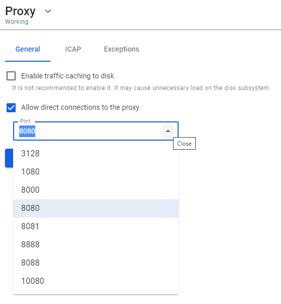
By default, caching of traffic to disk is disabled, but it is carried out in the server RAM. You can enable caching of web traffic to disk in Services -> Proxy, but we do not recommend doing this because of excessive load on the disk subsystem. As a rule, caching to RAM is sufficient.
Direct connections to the proxy server can be configured by checking the corresponding box in the section Services -> Proxy and specifying the IP address and port on the UTM side. Then these details should be specified on those LAN network devices whose web traffic needs to be passed through a proxy.
To configure HTTPS traffic filtering, you need to add a root UTM certificate to users' computers. Read more in the article on Setting up HTTPS filtering.
Below is a screenshot of the General tab in the Proxy section.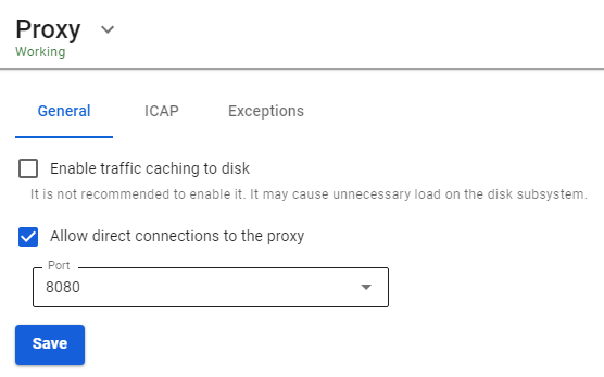
Role of Proxy Server in the Operation of SafeUTM Gateway
The proxy server, in addition to proxying web traffic, plays the role of a master service for several services related to processing, monitoring, and accounting for user web traffic on the gateway, namely:
- Antivirus for web traffic (ClamAV).
- Web traffic reporting service for users.
- Content filter.
Direct Connections to Proxy Server
This mode is used when SafeUTM is not the default gateway for network clients.
Setting up the mode
- Specify the SafeUTM local IP address as a web proxy on the local network on client devices. It is possible to use a proxy server for all protocols.
- In the proxy settings on SafeUTM, the IP address and port for direct connections to the proxy must be specified (you can select ports from the list: 3128, 1080, 8000, 8080, 8888, 8081, 8088, and 10080).
In this mode, UTM will be able to provide hosts with web content and traffic on other ports (by default on all, if necessary, you can close the ports with a firewall), in case of necessity performing accounting (quotas), monitoring and checking web traffic for viruses, content and malicious content if the following conditions are met:
- SafeUTM server has Internet access (its external interface must be in a range that does not overlap with the local subnet and have access to the Internet).
- Authorization of the web traffic consumer host on the UTM server by one of the authorization types supported by UTM.
- Explicit indication of the web proxy address to the host (in the proxy server settings in browsers). For Single Sign-On authorization via Active Directory, you must specify the SafeUTM domain name in the settings, and not its IP address.

If it is not possible to specify a proxy server in the program settings for Windows or Mac OS X, then you can use third-party software to route all workstation traffic to the proxy server. For example, Proxifier provides such an opportunity. For more information on how to configure Proxifier for direct connections to the proxy server, see an article by following the link.
Exclusion of Resources from Proxy Server Processing
On the Exceptions tab, it is possible to exclude resources from processing by the proxy server and all related services (content filter, web reporting, antiviruses).
- Source Networks: The proxy server is excluded from processing requests from the specified internal networks or IP addresses.
- Destination networks: The proxy server is excluded from processing requests to external networks or IP addresses (usually addresses of websites or web services).
We strongly discourage you from excluding the ENTIRE LAN from proxy server processing.
When connecting directly to a proxy server, traffic cannot be excluded from proxy processing. You need to exclude traffic in the proxy server settings on the device (in the web browser or the proxy server system settings).
Configuring Proxy with Single Interface
If necessary, you can use SafeUTM as a proxy server with direct connections of clients to the proxy, with a single interface.
To do this, you need to perform the following settings:
- When creating a local interface in Services -> Network interfaces, Gateway needs to be specified:

- Allow direct connections to the proxy server on the tab Services -> Proxy by selecting the desired port from the list:

When using SafeUTM as a proxy server with direct connections to the proxy, most of the functions will work normally, but with some peculiarities:
- In the firewall rules for users, it is necessary to specify INPUT paths instead of FORWARD.
- In-depth traffic analysis by the intrusion prevention system and the application control module will be carried out only for traffic passing through the proxy server (part of the rules will not work).
- Exceptions from the proxy server must be made by means of the browser or routes on the end devices. Settings on tab Services -> Proxy -> Exceptions apply only to the transparent mode of operation of the proxy server.
Exclude IP Addresses from Proxy Server Processing
Setting up exceptions for the traffic of individual users or traffic to certain Internet resources from passing and processing by a web proxy available as part of UTM.
Resource exclusions from proxy server processing only work for transparent proxy mode. With direct connections to the proxy server, it is impossible to exclude anything from proxy processing.
Two types of exceptions can be configured:
- Exclusion of traffic of local UTM network hosts directed externally from proxy processing (Source networks).
- Exclusion of traffic of all hosts in the local network served by UTM to certain resources in external networks (Destination networks).
You can only specific IP addresses or IP networks.
Traffic excluded from proxy processing will not participate in Reports, and also cannot be tested for viruses and processed by the Content filter module. At the same time, such traffic will be checked by a firewall, intrusion prevention services, and application control.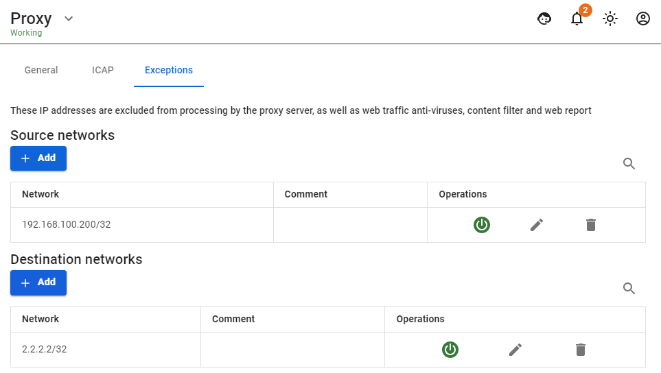
Programs Running on Protocols Other Than HTTP(S) via Web Proxy
Some programs that send traffic to their servers on ports 80 and 443, but at the same time work on protocols other than HTTP(S), cannot be processed by a web proxy server on UTM with HTTPS traffic filtering enabled. The traffic of such programs should be excluded from proxy processing in the Destination networks field.
Connecting to External ICAP Services
Sending HTTP(S) traffic for analysis to third-party servers using ICAP protocol.
In this case, traffic to these servers (which may include DLP systems, antiviruses, and web filters) is transmitted in decrypted form.
You can configure the connection to servers via ICAP in Services -> Proxy on the ICAP tab.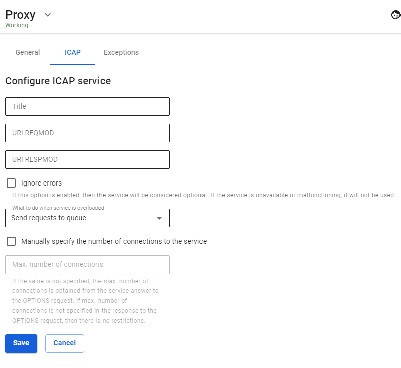
It is possible to establish a connection to several ICAP services simultaneously.
Reverse Proxy
Publishing local network web resources in such a way that they become available to consumers from the Internet.
Reverse proxy technology allows you to proxy web traffic in the opposite direction: from the Internet to the LAN, unlike the most commonly used option, from the LAN to the Internet. This approach replaced port mapping (DNAT) and expanded the possibilities for publishing web resources.
Reverse proxy differs from DNAT in that it works at a higher level (the HTTP application protocol instead of the IP network protocol) and allows for a more flexible implementation of resource publishing. The main parameter when publishing a web resource is the Requested address on the Internet. A request to UTM will be made from the external network via HTTP protocol and this URL. A reverse proxy allows you to "route" (HTTP-routing) such a request to an HTTP server on the LAN. Thus, having one resource A-record for the UTM external network interface you can publish several resources on the LAN by distributing them to several incoming URLs. If several A-records are associated with an external UTM IP address, then routing becomes even simpler, and incoming URLs are more convenient for resource visitors.
Creating and Configuring Rule
Configuring certificates for published resources does not require their manual download. Now SafeUTM itself sends a request to issue a Let's Encrypt certificate. The certificate issue may take up to 20 minutes. The issued certificates will be available in the TLS Certificates section.
To create a rule, go to Services -> Reverse Proxy and click Add. The form for adding a rule is divided into two subsections: Basic settings and Additional settings.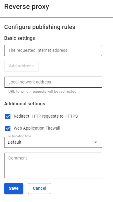
Basic Settings
- Requested Internet address – enter the IP address that will be requested by users. To add additional addresses, click Add address.
- Local network address – enter the IP address from the LAN to which users will be redirected.
If you specify 0.0.0.0 in the Requested Internet address line, the redirection will work from all external IP addresses to the address from the Local network address line.
If you specify any IP that does not belong to the external UTM interface, then such a redirect will work similarly to 0.0.0.0.
Additional Settings
- Redirect HTTP requests to HTTPS is used if your site only works via HTTPS protocol, but at the same time, you don't want to lose visitors who have accessed your site via HTTP.
- The Web Application Firewall function allows you to protect published resources using the SafeUTM web applications from various types of attacks (including SQLi, XSS, DoS, and others).
Web Application Firewall parses requests to the site and blocks attacks on vulnerable components of the web application (in particular, the types of attacks included in the OWASP TOP-10). When activating this module, attackers who are scanning the site for vulnerabilities will also be blocked using the brute force attack protection module.
- Field Publication type allows you to choose one of the following types: Standard and Outlook Web Access. The Outlook Web Access type is used for Microsoft Exchange publishing.
In the fields Requested address on the Internet and Address in the LAN for the Outlook Web Access type, specify only domains https://yourdomain/ without the rest of the URL (it is not used when publishing in this way).
! When publishing Outlook Web Access, do not enable the Web Application Firewall. Their collaboration will be possible in the next versions.
If you have a trusted SSL certificate for the domain through which a request to the published resource will go from outside, then you can upload it to the section Services -> TLS Certificates by clicking Add.
Domain names specified in the field Requested Internet address must resolve to the external IP address of the UTM server. Domain names specified in the field Local network address must resolve to the IP addresses of the published resources by the UTM server itself.
CMS Publication
So far, we have tested and officially support the publication of sites on two popular CMSs: Joomla and WordPress. The publication details of each CMS are described below.
Joomla
Joomla in the current implementation is published if you configure redirection from an external domain to a local domain without a prefix:
- Associate an additional domain name with an external UTM address specifically for Joomla publishing:
joomla.mydomain.com - Set up a publishing rule
joomla.mydomain.com->joomla.local:port(port is optional).
WordPress
WordPress in the current implementation is published only in the configuration when the same domain is configured in WordPress and in reverse proxy:
- Add an A-record for the company's domain
wordpress.mydomain.compointing to an external UTM IP address. - On the local server, the domain must be configured in the WordPress admin panel
wordpress.mydomain.comon the standard HTTP port. - Add a publishing rule to reverse proxy
wordpress.mydomain.com->wordpress.mydomain.com
DNS
A DNS server converts human-readable server names into IP addresses. SafeUTM includes a DNS server that does not require additional configuration in most cases.
DNS service on the SafeUTM server is configured in Services -> DNS. The service allows you to specify DNS servers in external networks through which domain names will be resolved (External DNS servers tab) requested from LANs. It is possible to specify third-party DNS servers (in local or external networks relative to UTM) with an indication of the specific DNS zones that these servers serve (Forward zones tab). The listed DNS server features can be used simultaneously.
Also, in the Master Zones tab, you can configure a full-featured DNS server that resolves names to IP addresses of network devices in the LAN.
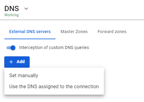
External DNS servers
For normal operation of name resolution on the Internet via SafeUTM, it is not necessary to specify DNS servers in this section. If DNS servers are not specified, the server will resolve names on the Internet using root DNS servers on the Internet. This configuration will not work if the upstream router intercepts DNS requests. In this case, we recommend:
- Specifying DNS servers manually (click Add -> Set manually and specify the IP address of the DNS server);
- Using Use the DNS assigned to the connection option, specifying the required connection;
Recommendations:
- The DNS server embedded in SafeUTM is a caching one. It is highly recommended to use it as a DNS server for your local network.
- Do not enter
8.8.8.8,1.1.1.1or similar ones unless absolutely necessary. SafeUTM will handle the resolution on its own without any intermediaries. - Do not specify a DNS server from your internal Active Directory server, even if it can resolve domain names on the Internet on its own. This, as a rule, is meaningless. When integrated with AD, SafeUTM will automatically configure everything necessary (forward zone) for AD operation and resolve the internal names of your domain. To resolve some special zones not related to AD, create a forward zone.
- Do not use DNS provided by your Internet provider unless absolutely necessary (do not specify either manually or through the interface selection option). SafeUTM will automatically configure everything you need to connect to PPTP/L2TP via a domain name. In practice, provider DNS exceeds TTL, and also takes a long time to respond. The only case when this is needed is the provider's special internal domain zones. In this case, create a forward zone.
- You can specify DNS servers engaged in filtering if necessary (SafeDNS).
- If all DNS servers are disabled or deleted, DNS will work fine - SafeUTM will resolve the names on its own.
- If the ISP or upstream device is intercepting DNS requests, then using the standard configuration with root servers is not possible, and you must either set the servers manually or use the DNS servers assigned to the connection.
Interception of DNS Requests
Enabling interception of DNS requests blocks the use of DNS-over-TLS (DoT), DNS-over-QUIC (DoQ), and DNS-over-HTTPS (DoH).
The product has the ability to intercept requests made through third-party DNS servers specified by users on workstations (in order to bypass locks, or due to incorrect configuration). To do this, enable the option Interception of custom DNS queries in External DNS servers.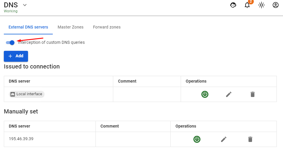
The option is enabled globally for all hosts in the LAN that access the Internet via SafeUTM. This allows you to avoid possible substitution of the resource address when resolving its domain in order to bypass resource locks. Also, interception of all users' DNS requests will allow you to control the process of resolving domain names on the Internet exclusively by means of UTM.
The intercepted request will be redirected to the UTM DNS server, and the response will be generated by the UTM DNS server, not the original DNS server. Interception of DNS requests also blocks the possibility of tunneling through DNS (DNS tunneling). Enabling the interception of custom DNS requests also blocks the use of DNS-over-TLS.
You can use the following third-party DNS servers for additional traffic filtering:
- SafeDNS
195.46.39.39,195.46.39.40 - Google DNS
8.8.8.8,8.8.4.4 - Open DNS
208.67.222.222,208.67.220.220,208.67.222.220,208.67.220.222 - Cloudflare DNS
1.1.1.1,1.0.0.1
DNS Server Management
You can turn off/on, edit or delete DNS servers in column Operations.
Forward zones
In this section, you can explicitly specify a DNS server to resolve the names of a specific DNS zone. By specifying the DNS server available on the network and the zone it serves, SafeUTM network clients are able to access the resources in this zone by the names of the domain it serves. For example, the IT department of an enterprise provides resources for employees in the zone in.metacortex.com under names realm1.in.metacortex.com , sandbox.metacortex.com and uses DNS server 10.10.10.10 for this.
To be able to access these resources by domain names, specify the provider's forward zone as an isp and then specify DNS server 10.10.10.10 in the Forward zone addition form.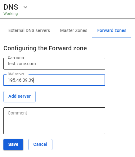
Master zones
Master zones with configured DNS records will allow you to use UTM as a name server inside your network infrastructure to access the IP addresses of hosts on the network by domain names.
The DNS server in SafeUTM is not accessible from outside for security reasons. To support external DNS zones, we recommend using third-party DNS hostings.
Do not use master zones to block access to sites, there are other means in SafeUTM to do this. Blocking in this way works inefficiently and does not allow you to selectively prohibit access by users or subnets. It also leads to problems with excessive caching.
The records format for setting up the master zone corresponds to the records format of the BIND DNS server.
Description of record parameters:
- $TTL – determines the caching time of positive responses (response in the form of the found IP address). The time is set in seconds or using abbreviations: m — minutes, h — hours, d — days, and w — weeks.
- $ORIGIN – defines the current domain name. The current value of $ORIGIN replaces the @ symbol in the record. The current value of $ORIGIN is appended to any name that does not end with a "dot".
- $SOA – describes the basic/initial settings of the zone, or defines this server’s area of responsibility. There should be only one SOA record for each zone and it should be the first one. The $SOA entry specifies the primary NS for the domain and the contact person's e-mail, and then in parentheses:
- Serial – The serial number of the zone file. When changing data, you need to change the serial number, which updates the zone on all servers. Use the following format: YYYYMMDDnn (year, month, day, nn is the sequential number of the change for the day). If you are already making changes to the zone file for the second time in a day, specify "nn" equal to 01, the third one will be 02, etc.
- Refresh – specifies how often secondary servers should poll the primary one to find out if the zone’s serial number has increased.
- Retry – waiting time after a failed polling attempt.
- Expiry – the maximum time during which the secondary server can use the information about the received zone.
- TTL – the minimum time during which data remains in the secondary server’s cache.
- $SRV – indicates the servers providing operation of certain services in this domain (for example, Jabber and Active Directory).
- $NS –the DNS server servicing this domain. A minimum of two of them are needed, and they should be located in different subnets, or better yet, in different places geographically. Specify the primary server first.
- $PTR – displays the IP address in the domain name.
- $MX – describes mail gateways (usually one) to which all mail from this domain will be delivered. Priority is set for each gateway (by default it is 10). Usually, the domain name of the mail gateway looks like this: example.com. There must be corresponding A-records for MX hosts.
- $A – map the hostname (domain name) to an IPv4 address. One A-record must be made for each network interface of the machine.
- $AAAA – similar to record A, but for IPv6.
- $CNAME – displays the alias to the real name (for redirection to another name).
All resource records can be found here.
An example of the record is shown in the screenshot below: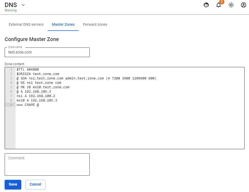
A few examples of records in the master zone:
1. Zone name: ms
$ORIGIN ms.
$TTL 600
@ SOA ns1.ms. administrator.ms. ( 4 7200 3600 1209600 600 )
@ NS ns1.ms.
@ MX 10 mx10.ms.
@ A 192.168.0.250
ns1 A 192.168.0.250
mx10 A 192.168.0.250
www CNAME @
2. Zone name: example.com
$TTL 86400
@ SOA localhost. root.localhost. ( 991079290 28800 14400 3600000 86400 )
@ NS my-dns-server.example.com.
my-dns-server A 1.2.3.4
DHCP Server
The DHCP server is used to automatically assign IP addresses to network devices on the LAN.
SafeUTM interface allows you to configure a range of IP addresses for automatic assignment, as well as to form static bindings of IP addresses to MAC addresses of these devices. Network devices on the local network must be configured to automatically receive network details from the DHCP server. Thus, clients send a broadcast request to a LAN segment, and the server intercepts and sends responses to these requests containing the necessary settings for the client.
A static IP address must be configured on the local SafeUTM interface participating in the distribution of addresses.
Configuring Server
In order to configure DHCP for the local interface, you need to go to Services -> DHCP server and click Add.
As a rule, the SafeUTM server is the gateway and DNS server for all LAN network devices, so in most cases, the service configuration is limited to determining the range of IP addresses. If necessary, you can specify DNS servers, static routes, and WINS server addresses. The list of DHCP server parameters can be seen in the table below:
*If DNS interception is configured on SafeUTM, then name resolution will be performed using the server specified in the DNS interception settings.
If you set the checkbox in the Issue IP addresses specified in authorizations via IP without MAC checkbox, then IP addresses (with the exception of the rule with IP+MAC) used as a user authorization factor (Authorization section) will be issued by the DHCP server.
An example of configuring a DHCP server is shown in the screenshot below: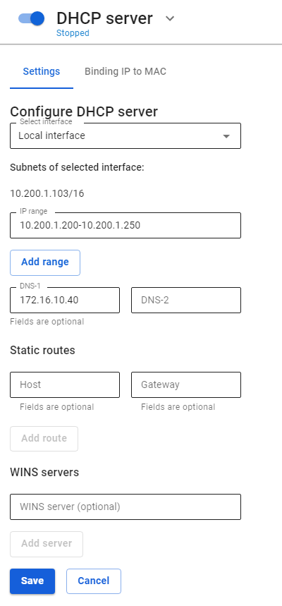
If no value is specified in the DNS-1 or DNS-2 field, then the DNS server will be SafeUTM for all network devices on the local network.
You can enable/disable, edit or delete rules for issuing IP addresses using control buttons in the Operations column.
Also, when using a DHCP server, do not forget to move the slider at the top of the screen near the inscription DHCP server to the Enabled position.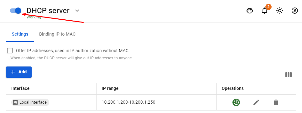
Configuring DHCP server with IP Binding to MAC
To configure the binding of the IP address to the MAC address in the DHCP server, follow these steps:
1. In the section Services -> DHCP server select the tab Binding IP to MAC.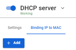
2. Create an IP-to-MAC binding rule: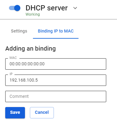
An example of the created binding rule is shown in the screenshot below: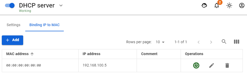
To check the created rule, on the computer with the MAC address specified in the rule, get an IP address via DHCP and check the result using the command ipconfig /all
Tips for configuring clients
Some devices provide a MAC address with hyphenated octets ( 01-02-03-04-05-06 ). In the SafeUTM settings, MAC address octets are separated only by colons ( 01:02:03:04:05:06 ). Therefore, be careful when coordinating the settings of client devices and the DHCP server on SafeUTM.
IPSec
Branches and Head Office
This type of connection allows you to combine the LANs of several SafeUTM servers.
Features of IPsec technology implementation in SafeUTM assume two roles of using SafeUTM:
- Head office – SafeUTM must have a public address on the Internet and accept connections from other SafeUTM (Branches), network equipment, or workstations (Remote Users).
- Branch office – SafeUTM connects to the Head Office and, as a rule, does not have a public address on the Internet. But if the Branch has a public address, then any other device can also be connected to it.
Setting up Connection Between Branch and Head Office
Head offices and Branches are added on the tabs with the same names in the section Services -> IPsec.
- Before creating a connection between the Branch and the Head Office, make sure that the time zone is correctly configured on each of the connected parties. It is impossible to establish a connection without this.
- Before configuring IPsec, it should be taken into account that for it to work, no IP subnets involved in connections, including the networks of the Head Office and all Branches, should overlap and, moreover, coincide.
- Networks of local interfaces of the Head offices and Branches to which you want to give access, must be set statically.
- Before setting up the connection, you need to make sure that one of the servers has a public (white) IP address from the Internet provider. If it turns out that the Head Office does not have a public IP address, and the Branch has such an address, then the server roles for this connection should be reversed.
- When replacing/reissuing the root certificate in the TLS Certificates section, IPsec connections Head Office <-> Branch will stop working and they will need to be recreated.
Step 1. Creating a connection in a Branch
In order to create a connection on SafeUTM, which will act as a Branch, it is necessary to perform the following settings in the web interface of this UTM:
1. Open the section Services -> IPsec -> Branch office and click Add in the upper left corner of the screen.
2. Fill in the following fields:
- Head office name – maximum 42 characters.
- Head office's external address – the domain name or external IP address of the head office issued by the provider. If necessary, you can enter the Head office's additional address.
- Branch office LANs – the IP address of the Branch's subnet that will be available to users in the Head Office, in the IP address/mask format.

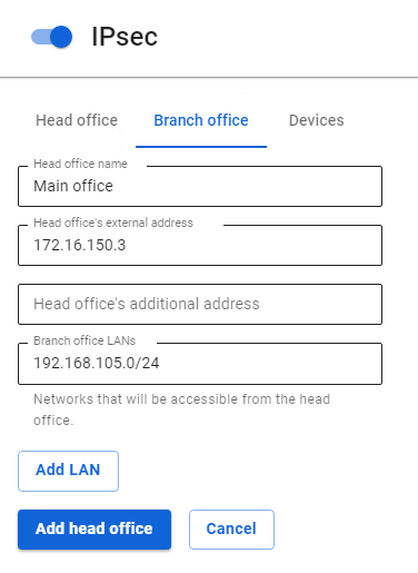
3. After filling in the fields, click Add head Office.
4. Click on the edit icon next to the added Head Office.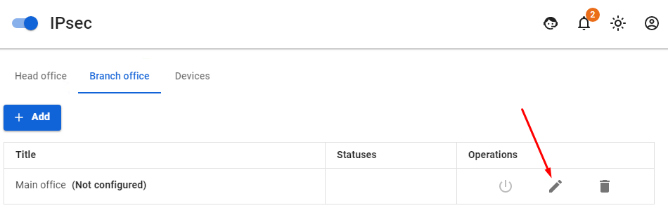
5. Copy the contents of the Branch office settings field. The contents need to be pasted when setting up the Head Office to which the connection is being made (see step 2).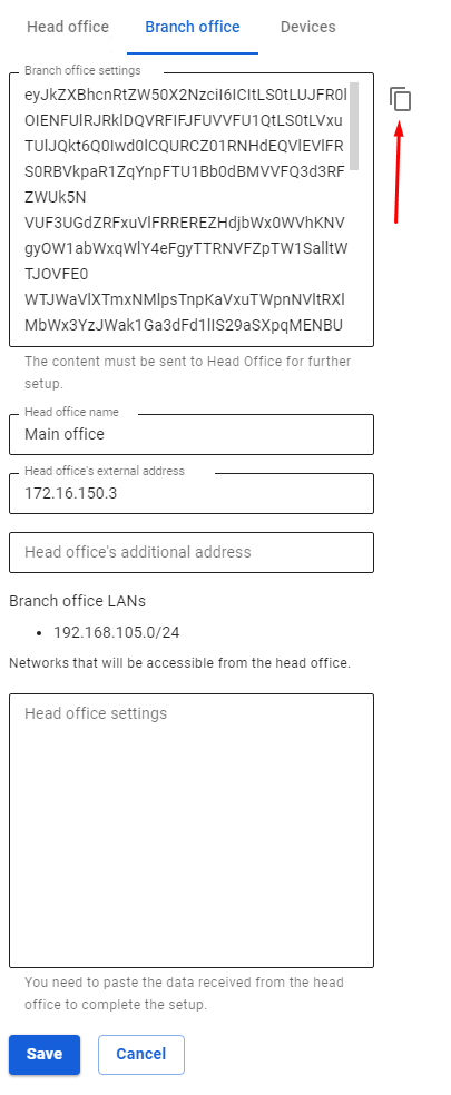
Step 2. Creating a connection in the Head Office
In order to create a connection on SafeUTM which will act as the Head Office it is necessary to perform the following settings in the web interface of this UTM:
1. Open the section Services -> IPsec -> Head Office and click Add.
2. Fill in the following fields:
- Branch office name – maximum 42 characters.
- Branch office settings – paste the settings that you copied from the Branch after completing step 1.

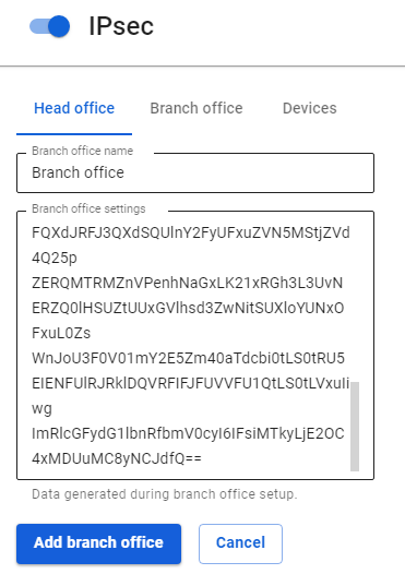
3. Click Add branch office.
4. Click the edit icon next to the added Branch.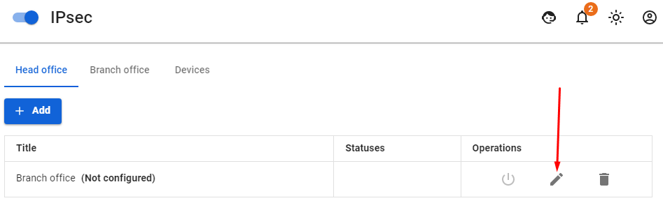
5. Select the LANs of the Head Office and click Save.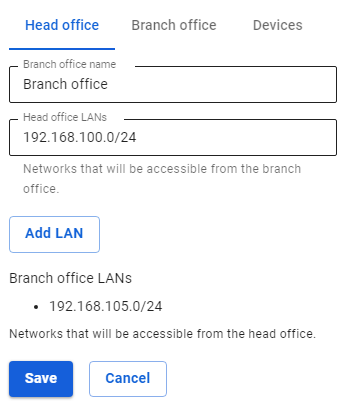
6. Go back to editing the added Branch and copy the contents of the Head office settings field. The contents need to be added to the Branch settings (see step 3).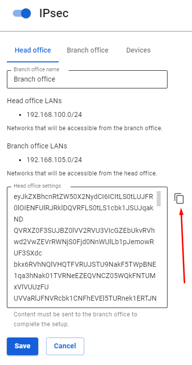
Step 3. Final setup of the Branch
In order to complete the creation of a connection on SafeUTM which will act as a Branch it is necessary to perform the following settings in the web interface of this UTM:
1. Open section Services -> IPsec -> Branch office.
2. Select the desired head office and click Edit.
3. Insert into the Head Office Settings field the settings text received from the Head Office during step 2.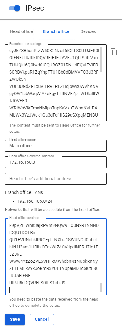
4. Click Save.
5. Open section Services -> IPsec -> Branch office on UTM acting as a Branch and section Services -> IPsec -> Head Office on UTM acting as the Head Office and make sure that the connection to the Head Office is established. The confirmation Established should appear in a green frame.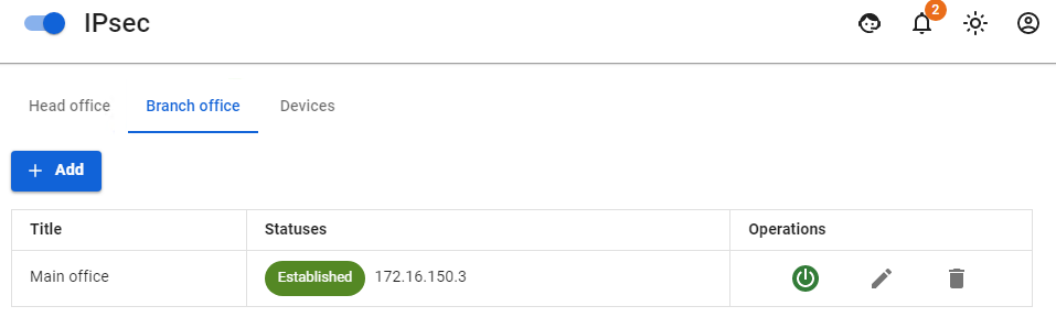
Routing of additional networks located behind the router in the local UTM network through an IPsec tunnel.
In order to configure the routing of networks located behind the router in the local UTM network, it is necessary to create a route to an additional network via the router's IP on SafeUTM (UTM, router and target host will be on the same network).
- If SafeUTM is behind NAT, then in order to work with IPsec you need to forward ports 500 and 4500 UDP.
- When installing an IPsec tunnel between SafeUTM servers (Branch and Head Office), 256-bit AES encryption is always used, as it is common and very reliable.
Connecting Devices
Description of options for connecting various routers (Mikrotik, Zyxel Keenetic, etc.) to SafeUTM for site-to-site VPN using IPsec IKEv2 protocol.
Devices that are not described in this manual as a rule can be connected using similar settings.
When combining networks using a VPN, LANs in different offices should not overlap.
The choice of crypto algorithms on remote devices.
When configuring third-party devices, you must explicitly specify the crypto algorithms used for the connection. SafeUTM supports the most up-to-date and at the same time sufficiently secure algorithms that do not load the server and devices. At the same time, outdated algorithms and those considered unsafe (MD5, SHA1, AES128, DES, 3DES, Blowfish, etc.) are not supported. When configuring third-party devices, as a rule, you can enter several supported algorithms at the same time. In fact, one algorithm of each kind is needed. Unfortunately, not all devices support the best algorithms, so SafeUTM supports several at once. Find below the list of algorithms of each type in descending order of priority for selection.
- Phase 1 (IKE):
- encryption:
- AES256-GCM
- AES256
- integrity (hash):
- for AES256-GCM - not required, since integrity check is built into AEAD algorithms.
- for AES256, by priority: SHA512, SHA256.
- prf (random value generation function):
- as a rule, it is configured automatically, depending on the choice of integrity algorithms (therefore, in the example below, the value of prf is PRF-HMAC-SHA512).
- for AES-GCM, you may need to specify explicitly. In this case, by priority: AESXCBC, SHA512, SHA384, SHA256.
- DH (Diffie-Hellman Group):
- Curve25519 (group 31)
- ECP256 (group 19)
- modp4096 (group 16)
- modp2048 (group 14)
- modp1024 (group 2)
- Timeouts:
- Lifetime: 14400 seconds
- DPD Timeout (for L2TP/IPsec): 40 seconds
- DPD Delay: 30 seconds
- encryption:
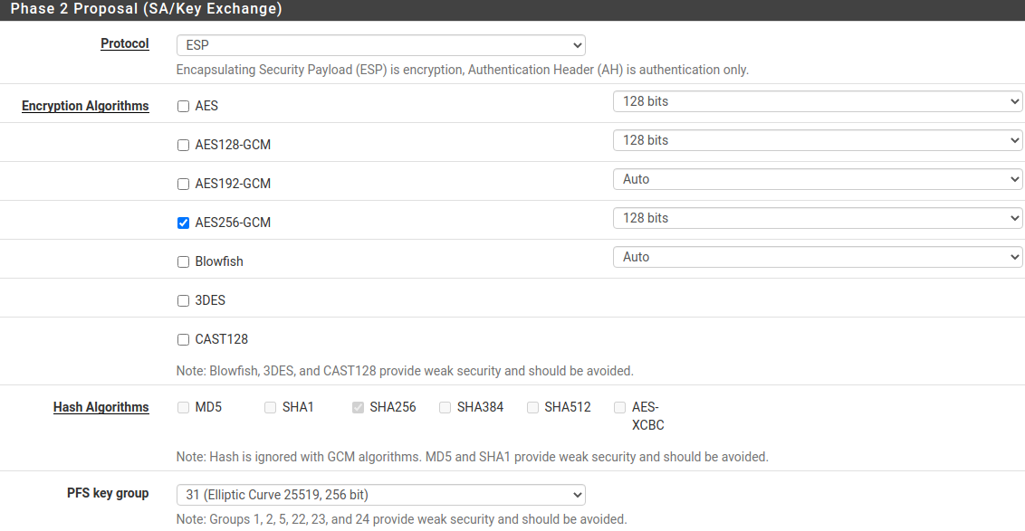
- Phase 2 (ESP):
- encryption:
- AES256-GCM
- AES256
- integrity:
- for AES256-GCM - not required, since integrity check is built into AEAD algorithms
- for AES-256, by priority: SHA512, SHA384, SHA256
- DH (Diffie-Hellman Group, PFS). ATTENTION! if not specified, it will connect, but rekey will not work after a while:
- Curve25519 (group 31)
- ECP256 (group 19)
- modp4096 (group 16)
- modp2048 (group 14)
- modp1024 (group 2)
- Timeouts:
- Lifetime: 3600 seconds
- encryption:
Example
- Phase 1 (IKE) (one of the lines is needed):
- AES256-GCM\PRF-HMAC-SHA512\Curve25519
- AES256\SHA512\PRF-HMAC-SHA512\ECP384
- AES256\SHA256\PRF-HMAC-SHA256\MODP2048
- Phase 2 (ESP) (one of the lines is needed):
- AES256-GCM\ECP384
- AES256\SHA256\MODP2048
An example of setting up a pfSense connection to SafeUTM via IPsec is shown in the screenshots below: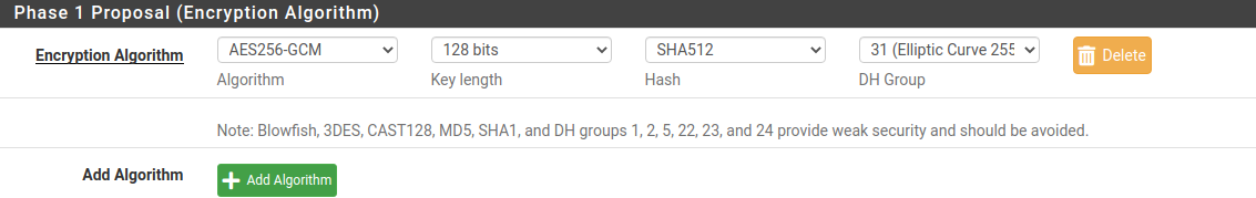
Connecting SafeUTM to MikroTik Using PSK
If there is a public IP address on the MikroTik device, follow the steps below to configure the SafeUTM connection to MikroTik.
Step 1.
Setting up SafeUTM
1. In SafeUTM, open the tab Services -> IPsec -> Devices, click on the icon (+), and fill in the following fields:
- Connection name – specify an arbitrary name for the connection. Maximum 42 characters.
- Connection type – select Outcoming, since the connection is made from UTM to MikroTik.
- Remote device address – specify the external IP address of the MikroTik device.
- Authentication type – select the PSK
- PSK – a random PSK key will be generated. You will need it to set up a connection in MikroTik.
- UTM identifier – the key you enter will be used to identify the outgoing connection.
- Home local network – list all UTM LANs that will be available in an IPsec connection, i.e. will be visible to the opposite side.
- Remote local networks – list all MikroTik LANs that will be available in an IPsec connection, i.e. will be visible to the opposite side.

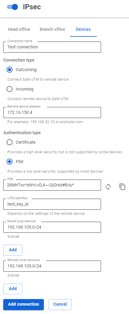
2. After filling in all the fields, click Add connection. Your connection will appear in the list of connections: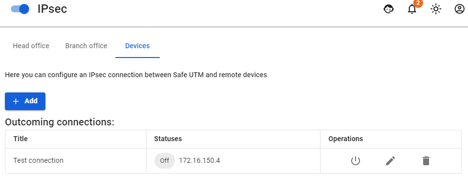
Step 2.
You can configure the MikroTik device in several ways - through the GUI, and through the device console.
Connecting MikroTik to SafeUTM Using PSK
If there is a public IP address on SafeUTM, follow the steps below to configure the connection of the MikroTik device to SafeUTM.
Step 1.
You can configure the MikroTik device in several ways - through the GUI, and through the device console
Step 2.
Setting up SafeUTM
1. In SafeUTM, open the tab Services -> IPsec -> Devices, click on the icon (+), and fill in the following fields:
- Connection name – specify an arbitrary name for the connection. Maximum 42 characters.
- Connection type – select Incoming, since the connection to UTM is being made.
- Authentication type – select the PSK type.
- PSK – insert the PSK key received from MikroTik.
- Remote side identifier – insert the MikroTik ID (Key ID parameter in
/ip ipsec peers). - Home local network – list all UTM LANs that will be available in an IPsec connection, i.e. will be visible to the opposite side.
- Remote local networks – list all MikroTik LANs that will be available in an IPsec connection, i.e. will be visible to the opposite side.

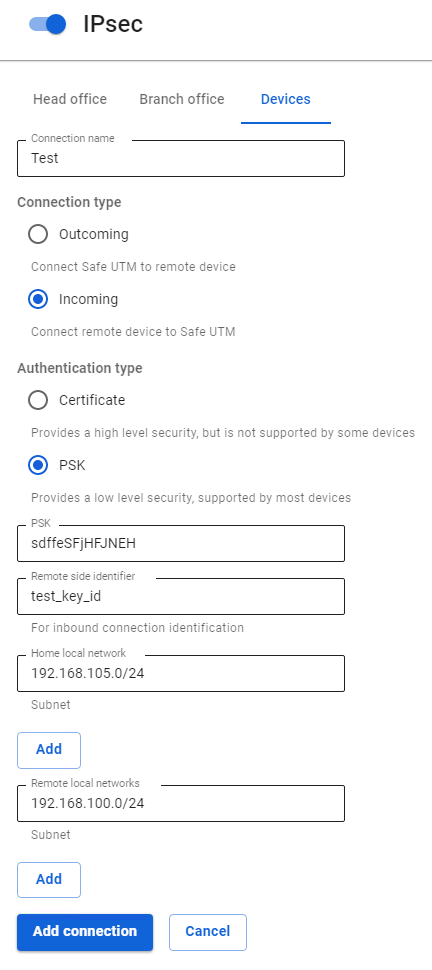
2. After filling in all the fields, click Add connection. Your connection will appear in the list of connections.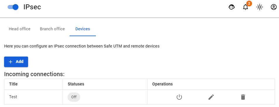
Connecting SafeUTM to MikroTik Using Certificates
Connection with certificates is used because it is more secure than a PSK connection, or in cases when the device does not support PSK.
For the correct operation of certificate connections, it is necessary that the time on MikroTik be synchronized via NTP. To do this, it is sufficient for the device to have access to the Internet.
The creation of outgoing IPsec connections using certificates to MikroTik below version 6.45 does not work due to the inability to use modern crypto algorithms in certificates.
Step 1.
Setting up SafeUTM
1. In SafeUTM, open the tab Services -> IPsec -> Devices, click on the icon (+), and fill in the following fields:
- Connection name – specify an arbitrary name for the connection. Maximum 42 characters.
- Connection type – select Outcoming, because the connection is made from UTM.
- Authentication type – specify the type of Certificate.
- Address of the remote device – specify the external IP address of MikroTik.
- Certificate signing request – a request will be generated which must be sent to MikroTik for signing.

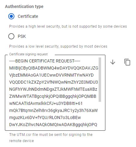
2. After the request is signed, you will need to continue configuring the connection in SafeUTM.
Do not close the settings tab!
Step 2.
Setting up MikroTik
At this stage, you should configure MikroTik to continue configuring UTM.
The UTM.csr file obtained from SafeUTM must be uploaded to the MikroTik file storage. To do this, open the File section, click Browse, select the file and upload it.
You can configure MikroTik in several ways - through the GUI, and through the device console.
Two files will appear in the MikroTik file system which you need to download in order to upload to UTM later.

The file of the type cert_export_device_<random character set>.ipsec.crt is a signed UTM certificate. The file of the type cert_export_mk_ca.crt is the root certificate of MikroTik.
At this point, the MikroTik setup can be considered complete.
Step 3.
Finishing up the SafeUTM setup
Go back to SafeUTM to the tab with the device connection settings and continue filling in the following fields:
- Signed UTM certificate – upload a signed UTM certificate to MikroTik.
- Remote Device Root Certificate – download the MikroTik root certificate.
- Home local networks – list all UTM LANs that will be available in an IPsec connection, i.e. will be visible to the opposite side.
- Remote local networks – list all MikroTik local networks that will be available in an IPsec connection, i.e. will be visible to the opposite side.

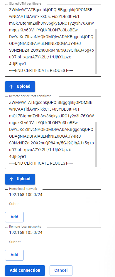
After filling in the fields, click Add connection. Your connection will appear in the list of connections.
Connecting MikroTik to SafeUTM by certificates
Connection with certificates is used because it is more secure than a PSK connection, or in cases when the device does not support PSK.
For the correct operation of certificate connections, it is necessary that the time on MikroTik be synchronized via NTP. To do this, it is sufficient for the device to have access to the Internet.
Step 1.
Setting up MikroTik
You can configure MikroTik in several ways - through the GUI, and through the device console.
Two files will appear in the MikroTik file storage which must be downloaded since they are required for further configuration.:
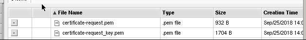
- File
certificate-request.pemis a certificate signing request. - File
certificate-request_key.pemis a private key.
Next, you will need to fill in the Certificate Signing Request field in SafeUTM, here is how to configure it.
Step 2.
Setting up SafeUTM
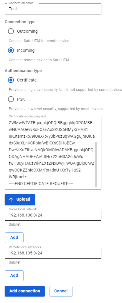
1. In SafeUTM, open the tab Services -> IPsec -> Devices, click on the icon (+), and fill in the following fields:
- Connection name – specify an arbitrary name for the connection. Maximum 42 characters.
- Connection type – select Incoming, since the connection to UTM is being made.
- Authentication type – select the type Certificate.
- Certificate Signing Request - Upload the signature request received from MikroTik.
- Home local network – it is necessary to list all UTM LANs that will be available in an IPsec connection, i.e. they will be visible to the opposite side.

2. After the settings, click Add connection. Your connection will appear in the list of connections. Click on the edit connection button to continue the setup.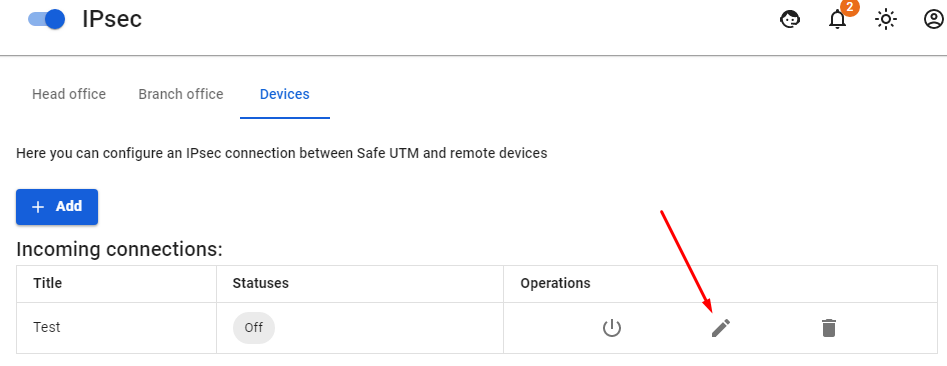
3. The connection settings editing area will appear. You need to download the files that are in the fields UTM root certificate and Signed device certificate for their subsequent use in MikroTik.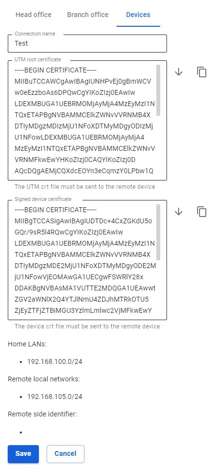
Problems when reactivating an incoming connection to SafeUTM
If after using this connection you turned it off, for example, as unnecessary, and when trying to re-enable the connection failed to be established, then most likely the remote device got into fail2ban (a tool that tracks attempts to access services in log files, and if it finds repeated unsuccessful authorization attempts from the same IP-address or host, it blocks further attempts).
Connecting Mikrotik to SafeUTM via L2TP/IPsec
Configure the connection by running the following commands:
- Edit the IPsec profile:
ip ipsec profile set default hash-algorithm=sha1 enc-algorithm=aes-256 dh-group=modp2048
- Edit IPsec proposals:
ip ipsec proposal set default auth-algorithms=sha1 enc-algorithms=aes-256-cbc,aes-192-cbc,aes-128-cbc pfs-group=modp2048
- Create a connection to SafeUTM:
interface l2tp-client add connect-to={server} profile=default disabled=no name={interface_name} password="{password}" user="{login}" use-ipsec="yes" ipsec-secret="{psk}"
Connecting users
Connecting remote users via L2TP/IPsec protocol.
The settings for connecting users (client-to-site VPN) are described in the article VPN connection L2TP IPsec.
Allow remote users to connect via L2TP/IPsec protocol
1. Go to Users -> VPN connections.
2. Check the item L2TP/IPsec connection. Unchecking the box disables all users connected via L2TP/IPsec and makes their connection impossible.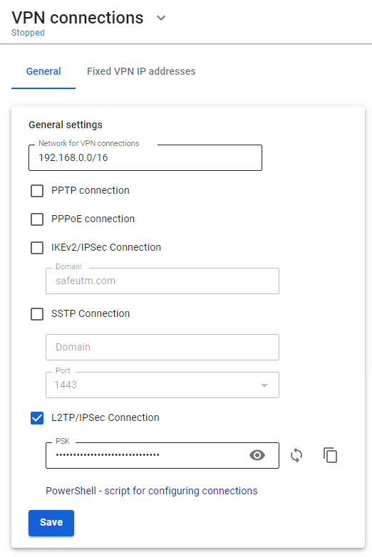
3. Change the default PSK. The pre-shared key is a line that will need to be entered in the L2TP/IPsec connection settings on end devices.
When changing the Pre-shared key, all remotely connected users will be disconnected. To restore connectivity, specify a new PSK on remote user devices.
Connecting offices (site-to-site)
PPTP VPN
Using the PPTP protocol, you can connect Branches that use outdated routers supporting only PPTP to the Head Office (if the device supports IPsec, it is recommended to use PPTP).
If possible, use a more reliable and secure protocol for connecting branches - IPsec. For details on setup, see the article Connecting devices.
For SafeUTM communication with SafeUTM, also use IPsec (see article Branches and Head Office).
The setup process consists of two stages:
- Server preparation and configuration of local networks.
- Creating VPN tunnels and configuring routing.
Server Preparation and Configuration of Local Networks
To combine local office networks, you need to ensure the uniqueness of the IP address space in them. Each office should have its own unique network. Otherwise, when creating a VPN tunnel, you may encounter incorrect routing.
Below is an example of combining networks of two offices. Configure your network and SafeUTM security gateway according to the data in the table below:
|
Parameter |
Office No1 (SafeUTM) |
Office No2 (Router) |
|
IP Address Space |
IP address: 192.168.0.0 Netmask: 255.255.255.0 |
IP address: 192.168.1.0 Netmask: 255.255.255.0 |
|
Local IP address |
IP address: 192.168.0.1 Netmask: 255.255.255.0 |
IP address: 192.168.1.1 Netmask: 255.255.255.0 |
Creating VPN tunnels and configuring routing
Internet gateway in Office No1
1. Create a user account, for example, "office2", on behalf of which the SafeUTM server in office No2 will connect to the SafeUTM server in office No1.
2. Allow the created account to have Allow remote access via VPN. This parameter can be activated in the section Users -> User & Group -> General by selecting the desired user.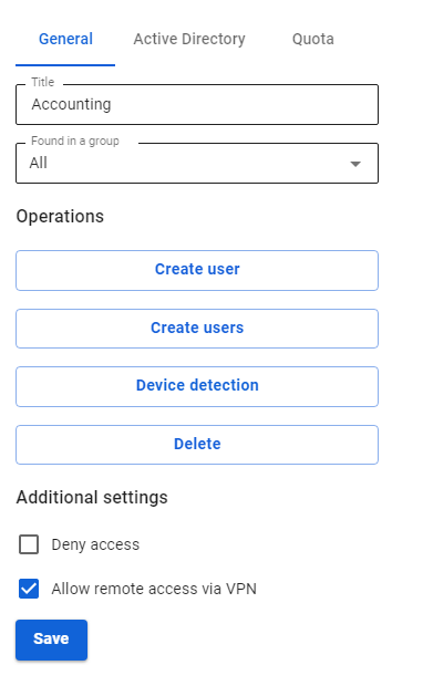
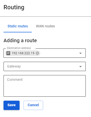
3. Add routes to the routing table. To do this, go to Services -> Routing -> Static routes and click the add button. We need to add the following route:
- Destination address:
192.168.1.0/255.255.255.0 - Gateway: user "office2"

Configuring the router in office No2
In the example, the settings are given for SafeUTM acting as a router. As a rule, routers from different manufacturers are configured similarly.
You need to create a VPN connection to a remote server and register a route to a remote network via a VPN connection. To do this, follow these steps:
- Create a new interface of the type Ethernet + PPTP. As a VPN server, specify the external IP address or domain name of office No1 and use the data of the account created on the server in office No1 (in our example, office2) as a username and password.
- Add routes to the routing table. To do this, in the web interface go to the section Services -> Routing and click the add button. Specify the required values and click Save. We need to add the following route:
Destination address:192.168.0.0/24Gateway: Select the Ethernet + PPTP interface that you have created.
Incoming Connection of Cisco IOS to SafeUTM via IPsec
Following the steps in this article, you can combine Cisco and SafeUTM networks via IPsec using PSK.
Find below the connection setup according to the scheme shown in the figure: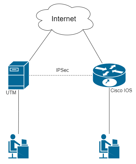
Step 1. Initial Setup of SafeUTM
Configure the local and external interfaces on SafeUTM. Detailed information can be found in the article Initial setup.
Step 2. Initial setup of Cisco IOS EX
Cisco configuration can be done through the device console (the configuration is described below)
1. Setting up the local interface:
enable
conf t
interface GigabitEthernet2
ip address {local IP Cisco} {subnet mask}
no shutdown
ip nat inside
exit
2. Configuring the external interface:
interface GigabitEthernet1
ip address {Cisco external IP} {subnet mask}
no shutdown
ip nat outside
exit
3. Check if there is a connection between the external interfaces of SafeUTM and Cisco. To do this, use the ping {external IP UTM} command in the Cisco console. The result of the command output is the presence of ICMP responses.
4. Creating an access list with local network addressing:
ip access-list extended NAT
permit ip {Cisco local subnet} {reverse subnet mask} any
exit
5. Configuring NAT (for more information on configuring this item, you can read the article on the official Cisco website):
ip nat inside source list NAT interface GigabitEthernet1 overload
exit
6. Saving configuration settings:
write memory7. Having saved the settings, make sure that there is Internet access from the Cisco LAN. To do this, visit any website (for example: https://www.cisco.com) from a device on the Cisco LAN.
Step 3. Configuring IKEv2+IPsec on Cisco
1. Creating a proposal (you can read detailed information on setting up this item in the article on the official Cisco website):
conf t
crypto ikev2 proposal ikev2proposal
encryption aes-cbc-256
integrity sha256
group 19
exit
2. Creating a policy (you can read detailed information on setting up this item in the article on the official Cisco website):
crypto ikev2 policy ikev2policy
match fvrf any
proposal ikev2proposal
exit
3. Creating a peer (key_id is the ID of the remote party, i.e. SafeUTM). Detailed information on setting up this item can be found in the article on the official Cisco website.
crypto ikev2 keyring key
peer strongswan
address {UTM external IP}
identity key-id {key_id}
pre-shared-key local {psk}
pre-shared-key remote {psk}
exit
exit
4. Creating an IKEv2 profile (you can read detailed information on configuring this item in the article on the official Cisco website):
crypto ikev2 profile ikev2profile
match identity remote address {UTM external IP} 255.255.255.255
authentication remote pre-share
authentication local pre-share
keyring local key
exit
5. Setting up encryption in esp:
crypto ipsec transform-set TS esp-gcm 256
mode tunnel
exit
6. Creating ipsec-isakmp:
crypto map cmap 10 ipsec-isakmp
set peer {UTM external IP}
set transform-set TS
set ikev2-profile ikev2profile
match address cryptoacl
exit
7. Configuring the crypto map on the external interface:
interface GigabitEthernet1
crypto map cmap
exit
8. Creating an access list for traffic between Cisco and UTM local networks:
ip access-list extended cryptoacl
permit ip {Cisco local subnet} {reverse subnet mask} {UTM local subnet} {reverse subnet mask}
exit
9. Adding traffic exceptions between Cisco and UTM local networks to the NAT access list (the deny rule should be higher than permit):
ip access-list extended NAT
no permit ip {Cisco local subnet} {reverse subnet mask} any
deny ip {Cisco local subnet} {reverse subnet mask} {local UTM subnet} {reverse subnet mask}
permit ip {Cisco local subnet} {reverse subnet mask} any
exit
end
10. Saving configuration settings:
write memoryStep 4. Creating an incoming IPsec connection on UTM
1. In the SafeUTM web interface, open tab Services -> IPsec -> Devices.
2. Add a new connection:
- Connection name – any.
- Type – incoming.
- Authorization type – PSK.
- PSK – specify the PSK key that you entered in Step 3 item 3.
- Remote side identifier – insert the Cisco ID (Key ID parameter in Step 3 item 3).
- Home local network – specify the SafeUTM local area network.
- Remote local networks – specify the Cisco local network.
3. Save the created connection, then click on Turn on
4. Check that the connection is established (your connection will appear in the list of connections, in column Statuses the word Installed will be highlighted in green).
5. Check for traffic between local networks (TCP and web).
The final configuration of Cisco IOS
The final configuration of IKEv2 IPsec on Cisco IOS should look like this:
crypto ikev2 proposal ikev2proposal
 encryption aes-cbc-256
 integrity sha256
 group 19

crypto ikev2 policy ikev2policy
 match fvrf any
 proposal ikev2proposal

crypto ikev2 keyring key
 peer strongswan
  address 5.5.5.5
  pre-shared-key local QWEqwe1234567890
  pre-shared-key remote QWEqwe1234567890

crypto ikev2 profile ikev2profile
 match identity remote key-id key-id
 authentication remote pre-share
 authentication local pre-share
 keyring local key

crypto ipsec transform-set TS esp-gcm 256
 mode tunnel

crypto map cmap 10 ipsec-isakmp
 set peer 5.5.5.5
 set transform-set TS
 set ikev2-profile ikev2profile
 match address cryptoacl

interface GigabitEthernet1
! external interface
 ip address 1.1.1.1 255.255.255.0
 ip nat outside
 negotiation auto
 no mop enabled
 no mop sysid
 crypto map cmap

interface GigabitEthernet2
! local interface
 ip address 2.2.2.2 255.255.255.0
 ip nat inside
 negotiation auto
 no mop enabled
 no mop sysid

ip nat inside source list NAT interface GigabitEthernet1 overload

ip access-list extended NAT
 deny   ip 2.2.2.0 0.0.0.255 3.3.3.0 0.0.0.255
 permit ip 2.2.2.0 0.0.0.255 any
ip access-list extended cryptoacl
permit ip 2.2.2.0 0.0.0.255 3.3.3.0 0.0.0.255Outgoing SafeUTM Connection to Cisco IOS via IPsec
Following the steps in this article, you can combine Cisco and SafeUTM networks via IPsec using PSK.
Find below the connection setup according to the scheme shown in the figure: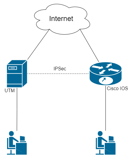
Step 1. Initial Setup of SafeUTM
Configure the local and external interfaces on SafeUTM. Detailed information can be found in the article Initial setup.
Step 2. Initial Setup of Cisco IOS EX
Cisco configuration can be done through the device console (the configuration is described below).
1. Setting up the local interface:
enable
conf t
interface GigabitEthernet2
ip address {Cisco local IP} {subnet mask}
no shutdown
ip nat inside
exit
2. Configuring the external interface:
interface GigabitEthernet1
ip address {Cisco external IP} {subnet mask}
no shutdown
ip nat outside
exit
3. Check if there is a connection between the external interfaces of SafeUTM and Cisco. To do this, use the ping {external IP UTM} command in the Cisco console. The result of the command output is the presence of ICMP responses.
4. Creating an access list with local network addressing:
ip access-list extended NAT
permit ip {Cisco local subnet} {reverse subnet mask} any
exit
5. Configuring NAT (for more information on configuring this item, you can read the article on the official Cisco website):
ip nat inside source list NAT interface GigabitEthernet1 overload
exit
6. Saving configuration settings:
write memory7. Having saved the settings, make sure that there is Internet access from the Cisco LAN. To do this, visit any website (for example: https://www.cisco.com) from a device on the Cisco LAN.
Step 3. Configuring IKEv2+IPsec on Cisco
1. Creating a proposal (you can read detailed information on setting up this item in the article on the official Cisco website):
conf t
crypto ikev2 proposal ikev2proposal
encryption aes-cbc-256
integrity sha256
group 19
exit
2. Creating a policy (you can read detailed information on setting up this item in the article on the official Cisco website):
crypto ikev2 policy ikev2policy
match fvrf any
proposal ikev2proposal
exit
3. Creating a peer (key_id is the ID of the remote party, i.e. SafeUTM). Detailed information on setting up this item can be found in the article on the official Cisco website.
crypto ikev2 keyring key
peer strongswan
address {UTM external IP}
identity key-id {key_id}
pre-shared-key local {psk}
pre-shared-key remote {psk}
exit
exit
4. Creating an IKEv2 profile (you can read detailed information on configuring this item in the article on the official Cisco website):
crypto ikev2 profile ikev2profile
match identity remote address {UTM external IP} 255.255.255.255
authentication remote pre-share
authentication local pre-share
keyring local key
exit
5. Setting up encryption in esp:
crypto ipsec transform-set TS esp-gcm 256
mode tunnel
exit
6. Creating ipsec-isakmp:
crypto map cmap 10 ipsec-isakmp
set peer {UTM external IP}
set transform-set TS
set ikev2-profile ikev2profile
match address cryptoacl
exit
7. Configuring the crypto map on the external interface:
interface GigabitEthernet1
crypto map cmap
exit
8. Creating an access list for traffic between Cisco and UTM local networks:
ip access-list extended cryptoacl
permit ip {Cisco local subnet} {reverse subnet mask} {UTM local subnet} {reverse subnet mask}
exit
9. Adding traffic exceptions between Cisco and UTM local networks to the NAT access list (the deny rule should be higher than permit):
ip access-list extended NAT
no permit ip {Cisco local subnet} {reverse subnet mask} any
deny ip {Cisco local subnet} {reverse subnet mask} {local UTM subnet} {reverse subnet mask}
permit ip {Cisco local subnet} {reverse subnet mask} any
exit

end
10. Saving configuration settings:
write memoryStep 4. Creating an outgoing IPsec connection on SafeUTM
1. In the SafeUTM web interface, open tab Services -> IPsec -> Devices.
2. Add a new connection:
- Connection name – any.
- Type – Outgoing.
- Authorization type – PSK.
- PSK – a random PSK key will be generated. You will need it to set up a connection in Cisco (see Step 3 item 3).
- UTM identifier – The key you entered will be used to identify the outgoing connection. Also, enter this ID in Cisco (see Step 3 item 3).
- Home local network – specify the SafeUTM local area network.
- Remote local networks – specify the Cisco local network.
3. Check that the connection has been established (your connection will appear in the list of connections, in the column Statuses the word Installed will be highlighted in green).
4. Check for traffic between local networks (TCP and web).
Final Configuration of Cisco IOS
The final configuration of IKEv2 IPsec on Cisco IOS should look like this:
crypto ikev2 proposal ikev2proposal
 encryption aes-cbc-256
 integrity sha256
 group 19

crypto ikev2 policy ikev2policy
 match fvrf any
 proposal ikev2proposal

crypto ikev2 keyring key
 peer strongswan
  address 5.5.5.5
  pre-shared-key local QWEqwe1234567890
  pre-shared-key remote QWEqwe1234567890

crypto ikev2 profile ikev2profile
 match identity remote key-id key-id
 authentication remote pre-share
 authentication local pre-share
 keyring local key

crypto ipsec transform-set TS esp-gcm 256
 mode tunnel

crypto map cmap 10 ipsec-isakmp
 set peer 5.5.5.5
 set transform-set TS
 set ikev2-profile ikev2profile
 match address cryptoacl

interface GigabitEthernet1
! external interface
 ip address 1.1.1.1 255.255.255.0
 ip nat outside
 negotiation auto
 no mop enabled
 no mop sysid
 crypto map cmap

interface GigabitEthernet2
! local interface
 ip address 2.2.2.2 255.255.255.0
 ip nat inside
 negotiation auto
 no mop enabled
 no mop sysid

ip nat inside source list NAT interface GigabitEthernet1 overload

ip access-list extended NAT
 deny   ip 2.2.2.0 0.0.0.255 3.3.3.0 0.0.0.255
 permit ip 2.2.2.0 0.0.0.255 any
ip access-list extended cryptoacl
permit ip 2.2.2.0 0.0.0.255 3.3.3.0 0.0.0.255Incoming pfSense connection to SafeUTM via IPsec
Following the steps in this article, you can combine pfSense and SafeUTM networks via IPsec using PSK.
The combined LANs should not overlap!
Setting up SafeUTM
1. In the SafeUTM web interface, open tab Services -> IPsec -> Devices.
2. Add a new connection:
- Connection name – any.
- Type – incoming.
- Authorization type – PSK.
- PSK – specify the PSK key to be used for the connection.
- Remote side identifier – any.
- Home local network – Specify the SafeUTM local area network that will be visible from the pfSense subnet.
- Remote local networks – Specify the pfSense local network that will be visible from the SafeUTM subnet.
3. Save the created connection, then click on the "Enable" button.
4. Two configuration files will be generated on SafeUTM in the /etc/strongswan/autogen/ folder. You need to go to the console and open the file of the type device_<number>.peer for editing.
5. From this file, you need to copy the value of the rightid line (approximate type –@#746573745f70736b). In the future, this value will need to be registered on pfSense.
6. The setup is complete, now let’s set up pfSense.
Setting up pfSense
1. In the pfSense web interface, go to tab VPN -> IPsec –> Tunnels.
2. Add a new connection:
- Key Exchange version – IKEv2.
- Internet Protocol – IPv4.
- Interface – Select the pfSense external interface that will be used to connect to SafeUTM.
- Remote Gateway – IP of the SafeUTM external interface.
- Description – any.
- Authentication Method – Mutual PSK.
- My identifier and Peer identifier – insert the value of the rightid line on SafeUTM here (see step 5 in setting up SafeUTM).
- Pre-Shared Key – insert the PSK key that was previously registered on SafeUTM.
- Encryption Algorithm: For SafeUTM version 13.0 and later, use the following parameters: Algorithm - AES256-GCM; Key length - 128 bit; Hash - SHA256; DH Group - Elliptic Curve 25519- 256.
All other values can be left by default.
3. Save the connection.
4. Click on the button Show Phase 2 Entries and add a new Phase 2. Specify here:
- Encryption Algorithm: For SafeUTM version 13.0 and later, use the following parameters: Algorithm - AES256-GCM; Key length - 128 bit; Hash - SHA256; DH Group - Elliptic Curve 25519- 256.
- Local Network – pfSense LAN which will be accessible from the SafeUTM subnet.
- Remote Network – SafeUTM LAN, which will be accessible from the pfSense subnet.
All other values can be left by default.
5. Save the connection.
6. Then you need to allow traffic to flow between the pfSense and SafeUTM local networks in the pfSense firewall (go to tab Firewall -> Rules -> IPsec and create two rules that allow traffic to flow between the SafeUTM and pfSense local networks).
Also, pay attention to the WAN firewall section – by default, incoming traffic from "gray" subnets is prohibited in it, so you need to remove this restriction.
7. Now go to tab Status -> IPsec (the created connection should appear there), and click on the Connect VPN button.
The setup is complete, the connection should be successfully established.
If the connection could not be established, and the pfSense firewall settings were made correctly, you should recreate the connection on UTM by specifying in the Key ID field the value that was specified in My identifier and Peer identifier for pfSense and try to connect again. No changes are required on the pfSense side.
Outgoing pfSense Connection to SafeUTM via IPsec
Setting up SafeUTM
1. In the SafeUTM web interface, open tab Services -> IPsec -> Devices.
2. Add a new connection:
- Connection name – any.
- Type – outgoing.
- Authentication type – PSK.
- PSK – specify the PSK key to be used for the connection.
- UTM identifier – any.
- Home local network – specify the SafeUTM local area network that will be visible from pfSense subnets.
- Remote local networks – specify the pfSense local network that will be visible from the SafeUTM subnet.
Setting up pfSense
1. In the pfSense web interface, go to tab VPN > IPsec > Advanced Options, and in the Child SA Start Action field select option None (Responder Only).
2. Add a new connection:
- Key Exchange version – IKEv2.
- Internet Protocol – IPv4.
- Interface – Select the pfSense external interface that will be used to connect to SafeUTM.
- Remote Gateway – IP of external interface SafeUTM.
- Description - any.
- Authentication Method – Mutual PSK.
- My identifier - My IP address.
- Peer identifier - KeyID tag. Enter the ID of the remote party, i.e. SafeUTM.
- Pre-Shared Key – enter the PSK key.
- Encryption Algorithm:
Algorithm - AES256-GCM;
Key length - 128 bit;
Hash - SHA256;
DH Group - Elliptic Curve 25519-256.
3. Save the connection.
4. Click the button Show Phase 2 Entries and add a new Phase 2 and enter the following values:
- Encryption Algorithm:
Algorithm - AES256- GCM; Key length - 128 bit; Hash - SHA256; DH Group - Elliptic Curve 25519-256. - Local Network – pfSense LAN which will be accessible from the SafeUTM subnet.
- Remote Network – SafeUTM LAN, which will be accessible from the pfSense subnet.
All other values can be left by default.
5. Save the connection.
6. Then you need to allow traffic to flow between the pfSense and SafeUTM local networks in the pfSense firewall (go to tab Firewall -> Rules -> IPsec and create two rules that allow traffic to flow between the SafeUTM and pfSense local networks).
7. Also pay attention to the WAN firewall section – by default, incoming traffic from "gray" subnets is prohibited in it, so you need to remove this restriction.
8. Now go to tab Status -> IPsec (the connection that was created should appear there), and click on the Connect VPN button.
The setup is complete, the connection should be successfully established.
If the connection could not be established, and the pfSense firewall settings are correct, you should recreate the connection to UTM by specifying in the field Key ID the value specified in My identifier and Peer identifier of pfSense, and try to connect again. On the pfSense side, no changes are necessary.
Connecting Keenetic via SSTP
You can connect routers with SSTP protocol support in site-to-site VPN mode.
If you do not need access from the central office to the network for Keenetic, then use the article Connecting Wi-Fi Keenetic Routers via SSTP on client-to-site connection.
Setting up SafeUTM
1. Enable and configure the port and domain for SSTP in Users -> VPN connections.
2. In Users -> User & Group create a special user for the remote router. Check the box Allow remote access via VPN. The username/password of the user will be used on the router, save or write them down.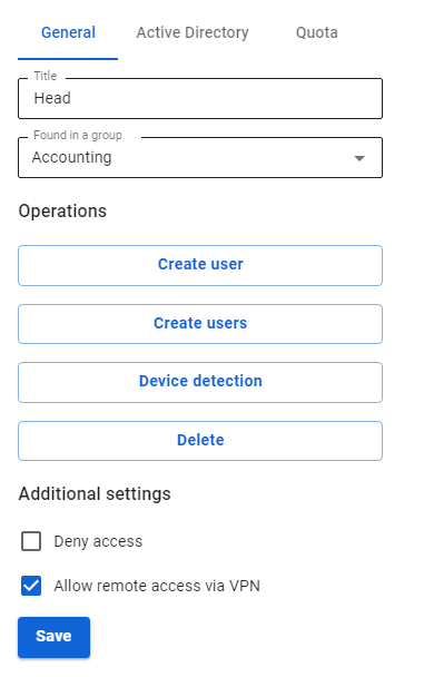
3. Register the routes to the remote network. For example, if the network behind the router is 192.168.10.0/24, you need to add the following route to the section Services -> Routing -> Static routes: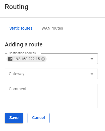
Configuring Keenetic Router
Configure the VPN connection of the Keenetic router according to the instructions for client-to-site connections.
Do not forget to follow all three steps:
- Set up a VPN connection.
- Set up routes.
- Configure DNS to resolve the local domain (if using Active Directory).
Verification and Possible Problems
To check the connection, use the ping and traceroute utilities.
If a VPN connection is established, but there is no access to the resources of one local network from another, use the instructions from the article to diagnose possible problems.
Most often, access is blocked in Windows due to network profile settings.
You can allow access to "non-local" networks in all profiles, by running the command in PowerShell (launched with elevated administrator rights): Enable-NetFirewallRule -Group "@FirewallAPI.dll,-28502"
Connecting Kerio Control to SafeUTM via IPsec
Following the steps of the article below, you can combine Kerio Control and SafeUTM networks via IPsec using PSK.
The combined LANs should not overlap!
Setting up SafeUTM
1. In the SafeUTM web interface, open tab Services -> IPsec -> Devices.
2. Add a new connection and fill in the following fields:
- Connection name – specify an arbitrary name for the connection. Maximum 42 characters.
- Type – select Incoming.
- Authentication type – select the PSK type.
- PSK – specify the PSK key to be used for the connection.
- Remote side identifier – specify the key that will be used to identify the connection on Kerio.
- Home local network – Select the SafeUTM LAN that will be visible from the Kerio Control subnet.
- Remote local networks - specify the Kerio Control LAN that will be visible from the SafeUTM subnet.
3. Save the created connection, then activate the connection by clicking on the Enable icon in the column Operations.
4. The setup is complete, Kerio Control needs to be configured.
Configuring Kerio Control
1. By default, Kerio Control uses IKEv1 to create connections to third-party devices. You can enable IKEv2 via the console. To do this, follow these steps:
1.1. Connect to Kerio Control via SSH.
1.2. Go to the folder /var/winroute
1.3. Open winroute.cfg file for editing.
1.4. In it, find the section starting with the text <table name="Firewall">
1.5. In this section, find the line <variable name="IKEVersion">ikev1</variable> and change ikev1 in it to ikev2
1.6. After that, it is advisable to restart the server and make sure that the changes in the settings are saved.
2. In the section Traffic rules, allow VPN services traffic.
3. Then go to the section Interfaces and click Add. In the drop-down list, select VPN tunnel...
4. The connection creation window will open. In it, select:
- Type – IPsec.
- The name is arbitrary.
- Activate Enable this tunnel.
- Select type Active and in the field below it, enter the IP address of the SafeUTM external interface that will be used for the connection.
- Select the Predefined key and enter the PSK key that will be used to connect.
- Local ID - specify the key that was set in the Remote side identifier field (p. 2);
- Remote ID - specify the IP address of the SafeUTM external interface;
- Under setting the ciphers, click on Edit. Set ciphers as in the screenshot:

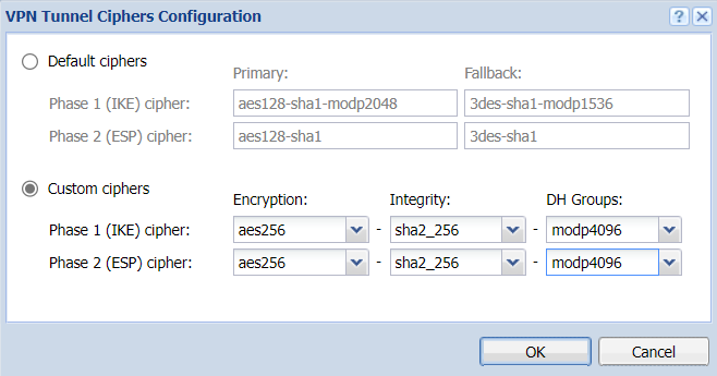
An example of the final settings is shown in the screenshot below.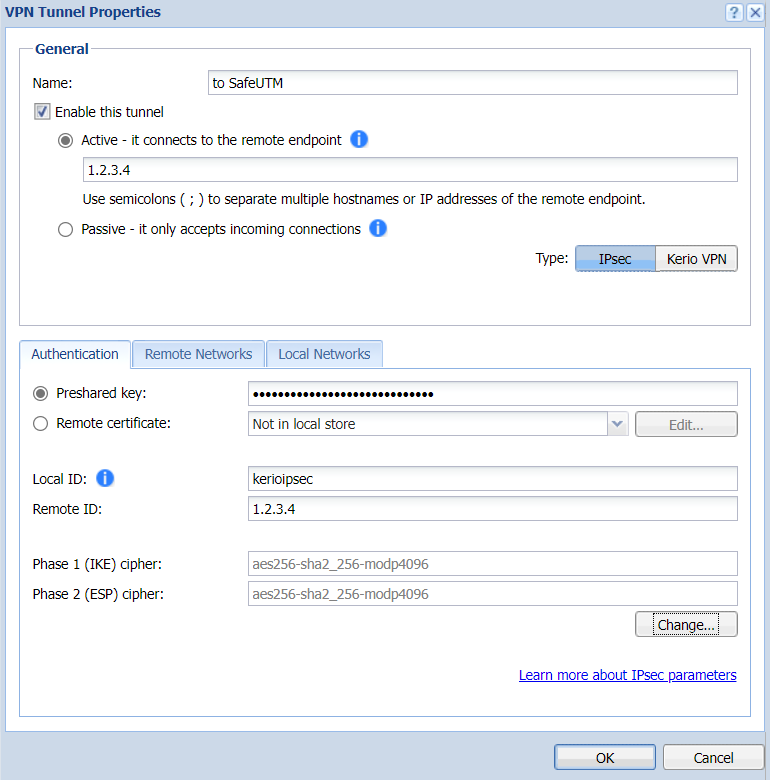
5. Go to the section Remote networks, click Add and enter the information about SafeUTM local network, which will be visible from the Kerio Control subnet.
6. Then in the section Local networks either click on the button Use automatically defined local networks, or configure networks that will be visible from the SafeUTM subnet manually, as in the previous step.
7. Setup is complete. After adding a new interface, you need to click Apply. After that, the connection should be successfully established, and the information about this is displayed in the table in the Interfaces section.
In case of problems, first of all, pay attention to Kerio Control firewall settings.
Connecting Keenetic via IPsec
On the SafeUTM side, configure the connection settings in the Services -> IPSec -> Devices section.
On the Keenetic device side, use the following encryption protocol settings:
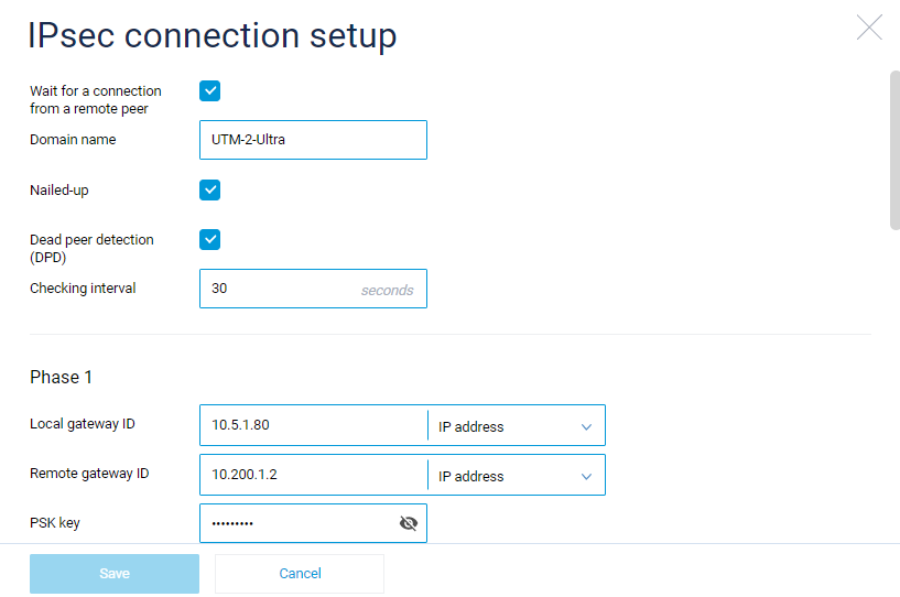
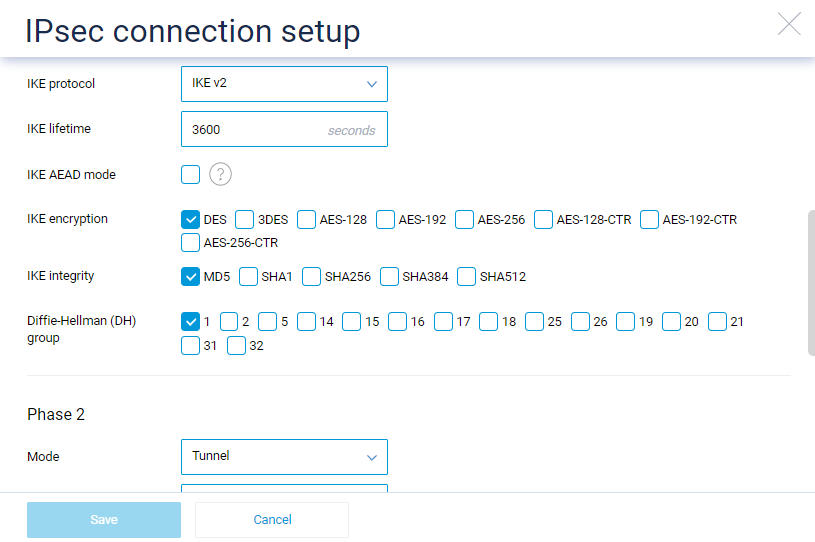
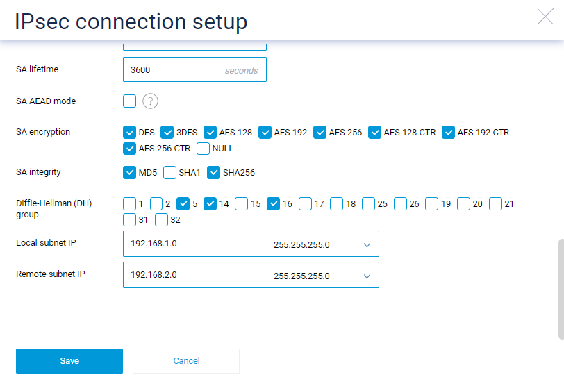
Certificates
TLS Certificates
Section with information about SSL certificates.
This section displays SSL certificates/certificate chains, the list of which is formed by the following modules: reverse proxying module, IKEv2, SSTP VPN servers, web interface, web authorization, mail, etc.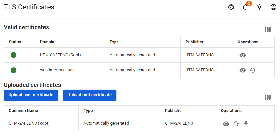
Valid certificates
The table Valid Certificates shows the ones generated automatically, as well as the downloaded certificate chains used by SafeUTM.
If the same certificate chain is listed in several rows of the Valid Certificates table, then this chain is used by several modules.
Downloaded certificates
The Downloaded Certificates table shows all downloaded certificate chains, as well as the SafeUTM root certificate. For more information, see Uploading your SSL certificate to server.
To view basic information about the certificate (serial number, expiration date, etc.), click the eye icon.
How is the certificate issued?
- A local certificate chain is created, and signed by a root (self-signed) certificate.
- Simultaneously with the creation of a local certificate chain, a request is sent to issue the chain to Let's Encrypt.
- If the Let's Encrypt certificate chain is successfully issued, it will replace the local chain.
- If the Let's Encrypt certificate chain issue fails, then the local certificate chain will be used.
How is the certificate reissued?
When reissuing a non-root certificate chain, UTM will try to update the chain as follows:
- It checks the downloaded certificates. If the certificate is found, it will replace the previous chain with the found downloaded one.
- If there are no downloaded certificates, then SafeUTM will turn to Let's Encrypt to issue a new certificate chain.
- If the chain from Let's Encrypt is received, it will be displayed in the table.
- If it was not possible to get a chain of certificates from Let's Encrypt, then a local chain of certificates is created and signed by the root certificate.
When the root certificate is reissued, UTM will replace the previous certificate with an automatically generated root certificate.
Features
If you want to try again to get a Let's Encrypt certificate instead of a self-signed one, you need to click Reissue in column Management.
When replacing/reissuing the root certificate chain, IPsec connections Head office <–> Branch will stop working and they will need to be recreated.
If you want to replace an automatically issued certificate chain with your own, then when uploading your own certificate chain, the CN (Common name) of the last certificate in the chain must match the domain for which the certificate is being uploaded.
Let's Encrypt certificate is issued for 3 months and will be automatically reissued upon expiration.
From this section, you can download the root (self-signed) certificate by clicking on the corresponding link.
To upload an SSL certificate to the server, see the article Uploading your SSL certificate to server.
Uploading your SSL certificate to server
After purchasing a trusted SSL certificate from Certificate Authority (CA), you need to create a text file of the type:
-----BEGIN PRIVATE KEY-----
.....
.....
-----END PRIVATE KEY-----
-----BEGIN CERTIFICATE-----
.....
.....
-----END CERTIFICATE-----
-----BEGIN CERTIFICATE-----
.....
.....
-----END CERTIFICATE-----
-----BEGIN CERTIFICATE-----
.....
.....
-----END CERTIFICATE-----
This file consists of two logical blocks:
- The block with a private key and the block of certificates consisting of a root certificate, a domain certificate, and vendor certificates.
- The block with certificates that the CA will send you follows the block with the private key.
Be careful: in addition to the root and domain certificate, the CA will most likely send additional vendor certificates consisting of several additional certificates in one file (bundle). This bundle of certificates must be added after the main certificate is issued for your domain. The order of the blocks in the file can be represented as follows:
Private key
Certificate for domain
Certificate from the vendor-certificates bundle
4Certificate from the vendor-certificates bundle
...
The main (root) certificate
After that, you can upload the received file with the private key and certificate to UTM via the web interface. To do this, go to Services -> TLS Certificates.
The generally accepted standard for creating a certificate chain file can also be found here: https://www.digicert.com/ssl-support/pem-ssl-creation.htm.
Encrypted private key
Only the standard private key format is supported: decrypted PEM. Such a key starts with the line:
-----BEGIN RSA PRIVATE KEY-----
Sometimes the CA issues an encrypted private key using a passphrase. In this case, you need to decrypt (convert) the encrypted key into a regular one using the openssl utility or, if the CA provides other tools for this, use them. The list of parameters for calling openssl to convert the key into an unencrypted form depends on CA's key encryption technology and should be described in the instructions for installing the certificate from the CA. You cannot upload and use an encrypted private key on the SafeUTM server.
Instructions for Creating Certificate on Windows OS.
To create a certificate, follow these steps:
1. Download the OpenSSL program. Link to the program: http://slproweb.com/products/Win32OpenSSL.html.
2. Install OpenSSL.
3. If the certificate file is in pkcs12 format: (if it is in .pem format, then you can immediately proceed to Subparagraph d):
- a. Place this file in the directory C:\OpenSSL-Win64\bin (in the folder with the OpenSSL program installed).
- b. Open the command prompt.
- c. In the command prompt, go to the directory with the OpenSSL program installed.
- d. Enter command
openssl pkcs12 -in certificate.pkcs12 -out certificate.pem(with this command, you will convert the certificate to the desired format). certificate.pkcs12 is the source certificate that you received from the certification authority (hereinafter CA); certificate.pem is the result of the conversion. - e. Open the resulting file in a text editor (for example, in notepad).
- f. The file has the following structure:
```
 -----BEGIN CERTIFICATE-----
 ..............
 ..............
 -----END CERTIFICATE-----
 -----BEGIN ENCRYPTED PRIVATE KEY-----
 ..............
 ..............
 -----END ENCRYPTED PRIVATE KEY-----
```
or this structure:
 -----BEGIN CERTIFICATE-----
 ..............
 ..............
 -----END CERTIFICATE-----
 -----BEGIN PRIVATE KEY-----
 ..............
 ..............
 -----END PRIVATE KEY-----
If it is written in the certificate --BEGIN ENCRYPTED PRIVATE KEY--, then you need to decrypt it using the OpenSSL utility. Command to decrypt: openssl rsa -in certificate.pem -out certificate_decoded.pem. certificate.pem is the file that you received after conversion in Step d; certificate_decode.pem is the result of decryption. If in the certificate it says --BEGIN PRIVATE KEY--, then the certificate file has already been decrypted. You can proceed to the next step.
4. Create an empty file with extension .pem (my_certificate.pem).
5. Open it with a text editor.
6. Open the file that you got in Step 3 (certificate_decode.pem). From this file you need to copy the text of the type (private key):
-----BEGIN PRIVATE KEY-----
..............
..............
-----END PRIVATE KEY-----
7. Paste the copied text into the file created in Step 4 (my_certificate.pem).
8. Go to the file created in Step 3 (certificate_decode.pem). From this file you need to copy the text of the type (your domain certificate):
-----BEGIN CERTIFICATE-----
..............
..............
-----END CERTIFICATE-----
9. Paste the copied text into the file created in Step 4 (my_certificate.pem).
10. The CA, in addition to your certificate, should have sent you a certificate bundle (there may be several of them) and a root certificate. If you don't have these certificates, you can download them online or request them from your CA.
11. From the certificate bundle and the root certificate, copy the text of the type:
```text
-----BEGIN CERTIFICATE-----
..............
..............
-----END CERTIFICATE-----
```
12. Paste the copied text into the file created in Step 4 (my_certificate.pem). In the beginning, you will need to insert the text from the certificate bundle, and at the very end the text of the root certificate.
13. As a result, you will get a file of blocks:
```
Private key
domain certificate
Certificate from the vendor-certificates bundle
Certificate from the vendor-certificates bundle
.........
Root certificate
```
14. Upload the resulting file to UTM. To do this, go to Services -> TLS Certificates.