4.7. Setup - Server Management
- Administrators
- Central Console
- High availability
- Automatic Update
- Backup
- Terminal
- License
- Additional settings
Administrators
Managing Administrators
It is possible to set the credentials of several administrators of the SafeUTM server to access the settings web interfaces.
The pre-installed administrator account cannot be deleted, you can only change its data – name, and password – using the corresponding elements in the Management column.
You can create additional server administrators and manage accounts in the section Server Management -> Administrators.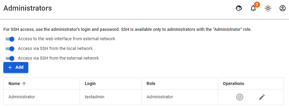
To add a new administrator, click Add and fill in the following fields:
- Name - Enter the name of a new administrator. The value must be 42 characters maximum.
- Login - Enter the login of a new administrator. The value must be 42 characters maximum.
- Password/repeat password - Enter the password of a new administrator. The value must be 10 characters minimum. We recommend using complex passwords containing Latin lowercase and uppercase letters, numbers, and special characters.
- Role - select the Administrator role or View only. When choosing View only role, the administrator will not be able to make any settings in the web interface, because when you try to make changes, a window with the error "Access denied" will appear.

Access to Web Interface from External Network and Remote Access via SSH
- To enable access from the external network, switch the slider to Enabled near item Access to web interface from external network. This function helps to administer SafeUTM remotely.
- To enable SSH access to the server from local or external networks, switch the slider to Enabled near the corresponding items (not recommended). Access is provided via TCP port 22. Password-guessing attempts are blocked automatically. Use the command local-menu to launch the menu, and command mc to launch the file manager.
For more information about configuring the connection to the web interface for remote access, see the article Remote Access for Server Management.
Administrator Password Recovery
For more information about administrator password recovery, see this article by following the link.
Central Console
Central Console
Helps to centrally manage UTM servers.
Safe Center is a central console that will help you administer multiple SafeUTM servers at once. Currently does not require licensing and has no restrictions on use. Automatically propagates security policies to all connected SafeUTMs, even if they were connected after the policies were configured.
Opportunities of Safe Center:
- Creation of security policy rules (firewall, content filter, etc.) and objects that are transferred to connected SafeUTM servers at the same time;
- The transition from Safe Center to the web interface of connected SafeUTMs;
- Management of administrator access rights. However, Safe Center administrators have access to connected UTMs, but connected UTM administrators do not have access to Safe Center.
Learn more about how security policies and objects work in the Policies and Objects articles.
Technical requirements for servers and virtual machines:
- RAM - 8 GB;
- UEFI;
- Disk space - 64 GB;
- Two processor cores;
- One network card;
- Supported hypervisors: KVM, ESXi, hyper-v
You can request the installation file from your Manager or Tech Support. The Safe Center installation process is similar to the SafeUTM installation process.
Connecting Safe UTM to Safe Center
If a cluster is used in the connected SafeUTM, it is enough to connect only the active node, the passive one will automatically accept this setting.
The network connection is made in the direction from SafeUTM to Safe Center, i.e. communication is also possible when SafeUTM is behind NAT.
To connect SafeUTM to Safe Center:
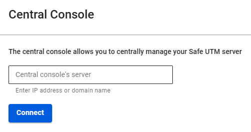
- Go to Server Management -> Central Console;
- Enter the IP address or domain name in the Server field and click Connect:
If the Safe Center IP address is listed instead of the domain name, upload the Safe Center root certificate to SafeUTM:
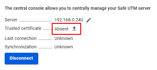
You can download the root certificate in the Safe Center, section Services -> TLS Certificates.
- In the Safe Center interface, go to the Servers section and confirm the connection.
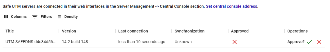
If the Safe Center server is behind NAT, enter the IP address or domain name in Server Management -> Additional settings -> Central Console's Address.
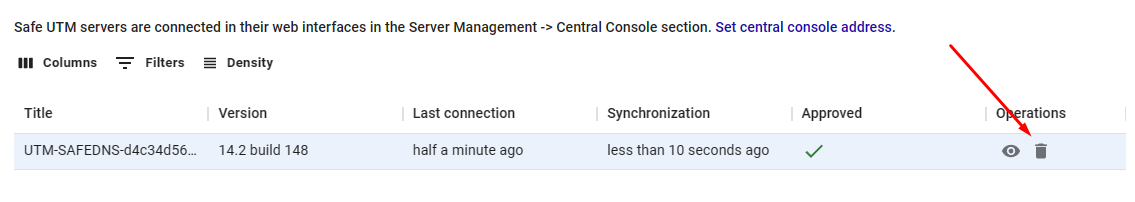
Removing the SafeUTM server from the Safe Center will break the binding in the SafeUTM interface:
Switching from the Safe Center web interface to the SafeUTM web interface
Safe Center provides two ways to switch to SafeUTM:
- Go to the Servers section and click on the eye icon:
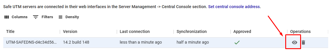
The SafeUTM web interface will open in a new tab.
- Click on the dropdown icon in the upper left corner and select the desired UTM:
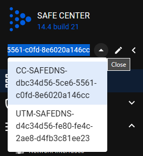
The SafeUTM web interface will open inside Safe Center window.
Policies
The principles of operation of the sections Firewall, Application Control, Content Filter, and Traffic Shaping with connected UTM are identical. Consider it using the Firewall section as an example.
Firewall
The Safe Center firewall contains only FORWARD and INPUT tables.
An example of adding rules in Safe Center: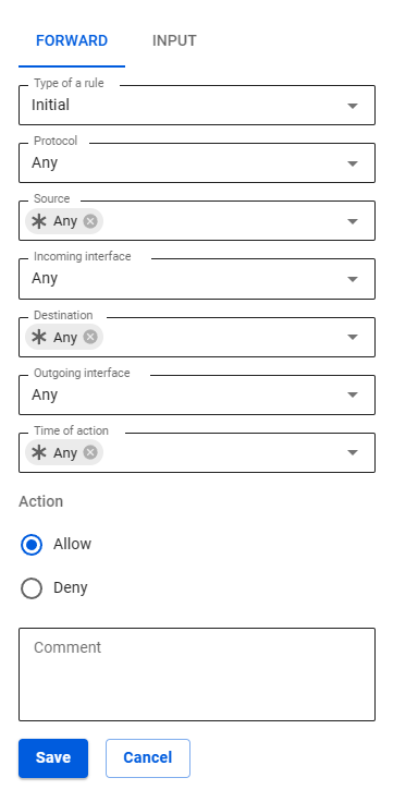
In Safe Center
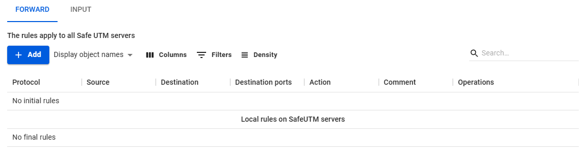
The Forward rules created in Safe Center are displayed in two tables: Initial and Final. These tables are divided by Local Rules on SafeUTM servers.
An example of an empty table:
An example of a completed table:

Local rules on SafeUTM servers are not visible in the Safe Center interface. To view, go to the Servers section, click on the eye icon in the line with the required SafeUTM, and go to the Firewall section.
In order for the created rule to be included in the Initial rules table, specify the Initial value in the Rule type line. If you want to place the rule in the Final rules table, select the Final value.
You cannot move rules between the Initial rules and Final rules tables.
In SafeUTM
The table in SafeUTM is visually divided into three parts: top, middle, and bottom.
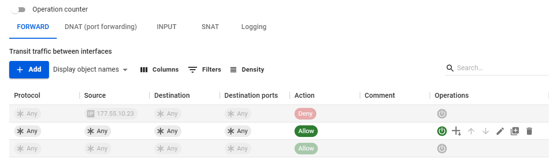
The rules from the connected Safe Center are transferred to the upper and lower parts. These rules cannot be managed in SafeUTM. The top part corresponds to the Initial rules table in the Safe Center. The lower part - the table Final rules.
The middle part is created by the UTM administrator in UTM itself and is not visible in the Safe Center interface.
Objects
Objects created in Safe Center are migrated to connected SafeUTMs. The SafeUTM administrator can use these objects to create rules.
When an object is deleted from Safe Center, the object is also deleted from SafeUTM. If a rule with a deleted object was created in SafeUTM, then this object will be marked with the Deleted icon.
The principle of creating and deleting objects in the Safe Center is consistent with the principles of SafeUTM. Detailed description in the article Objects.
Services
Network interfaces
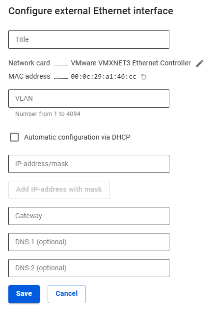
Unlike SafeUTM, only a local Ethernet interface is created in Safe Center. To do this, click Add, select a network card, and fill in the required fields:
- Interface name - Name to identify the interface;
- Network card - Network adapter that will be used to connect to the Internet provider;
- VLAN tag - VLAN ID. Such a network interface is considered a VLAN interface. Filled in if the network card is already in use;
- Automatic configuration via DHCP - Use if your ISP supports automatic configuration of the Ethernet interface via DHCP;
- IP Address/Mask - Assign multiple IP addresses to an interface if required. At least one IP address is required;
- Gateway - IP address of the gateway;
- DNS - Two fields are available to specify the DNS server (optional).
Routing
Routing works similarly to SafeUTM routing. Detailed description at the link.
DNS
The principle of operation of DNS in Safe Center is similar to the principle of operation of External DNS servers in SafeUTM. If the upstream router intercepts Safe Center DNS queries, then add external DNS servers.
Server Management
In the central console (Safe Center), the sections Automatic Update, Backup, and Terminal are similar to these sections in SafeUTM.
Administrators
In Safe Center, you can create several administrators with different roles:
- Administrator - an administrator with this role has access to all Safe Center functionality (more about features);
- Read-only - an administrator with this role cannot manage rules in Safe Center (create, change priority, etc.). But can switch to connected SafeUTMs and manage them.
All administrators (both Administrator and Read-Only) can delete connected SafeUTM from Safe Center.
There are two ways to connect to the SafeUTM web interface from the Safe Center located in the Safe Center:
- From the Servers section (by clicking on the eye icon);
- By clicking on the arrow in the upper left corner, and selecting the desired UTM:
It is not possible to log in to the connected SafeUTM with the Safe Center administrator login and password.
Additional Settings
The following settings are available in the section:
- Central console's address - the field is filled in if the Safe Center server is behind NAT;
- Time zone settings - changes take effect only after restarting the Safe Center;
- Language settings - changes take effect only after restarting Safe Center.
High availability
This section describes how to configure a cluster consisting of two SafeUTM servers.
Each of the two SafeUTM devices is called a node.
The cluster operates in active-passive mode. The node that processes traffic at a given time is active. In its turn, the backup node continuously monitors the status of the active node and transfers the current traffic processing tasks to itself in the absence of communication with the active node. Only one of the nodes can handle traffic at any time.
Network interaction between nodes is carried out via a separate physical channel, for which one physical network card is reserved on each of the nodes. This communication channel is called A cluster network. A keep-alive mechanism is used to maintain communication between nodes.
Node switching occurs in case of failure (complete freezing or reboot) of the active node, as well as in case of loss of communication between nodes over the cluster network.
The cluster has one shared IP on the internal interface and another shared IP on the external interface. Since the MAC addresses of both nodes are different, the Gratuitous ARP mechanism is used.
For the cluster to work correctly, there must be constant communication between nodes.
Cluster operation features:
- Mail will be available for operation only in the mail relay mode. Mailbox storage is disabled.
- Reporting, logging, and monitoring data are not synchronized between nodes. Each node has its own data stored.
- Recovery from backups is not possible.
- It is forbidden to change the names of servers.
- It is forbidden to delete and add network interfaces, but it is ALLOWED to disable and edit them.
- If the provider has the binding by MAC address, then there will be no Internet access when switching nodes.
- To configure clustering, only one SafeUTM license is needed.
Requirements
To create a cluster, the following requirements must be met:
- There can be only 2 SafeUTM nodes in a cluster.
- Both nodes must have the same version of the system identical up to the build number.
- Interfaces on each SafeUTM server must be connected to the same switch or LAN segment (for more information, see step 2, point 2).
- The number of physical network cards used on both servers must be the same. If this condition is not met, you cannot create a cluster.
Configuring Cluster
If at the time of cluster creation you already have a configured SafeUTM, then we recommend choosing it as the active node. All backup node settings will be deleted during cluster creation.
Step 1 - Configuring the backup node
If you have just installed the SafeUTM server
1. When you enter the local menu of the backup node, you will see the following message: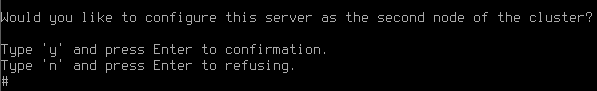
2. Type y and press Enter.
3. Select the network card: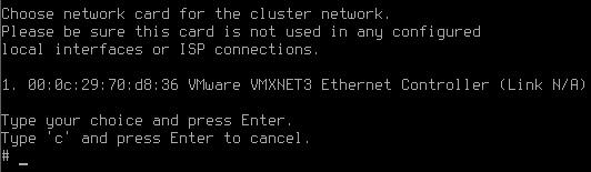
4. Confirm cluster creation by typing y and pressing Enter: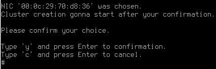
5. UTM will offer to change the name of the server. If you answer the question "Change server name?" positively, an inscription will appear with the suggestion to enter a new server name.
The minimum number of characters in the name is 2.
The maximum number of characters in the name is 42.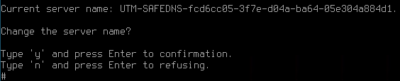
Having entered a new name, press Enter to continue the dialog.
6. A message will appear stating that the cluster creation process has started: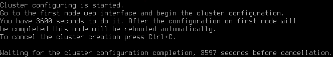
You need to go to the web interface of the active node and perform the settings (see point Configuring Active Node). 3,600 seconds are allocated for this.
If you are creating a backup node from an already installed SafeUTM server with a license and Internet access
1. Go to the local menu.
2. Select Cluster Creation: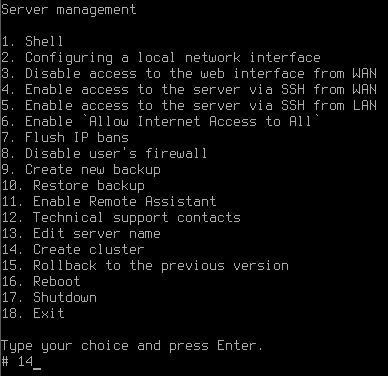
3. Select a free physical network card to create a cluster network and confirm the selection: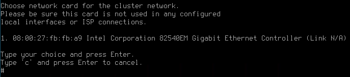
4. Confirm cluster creation by typing y and pressing Enter: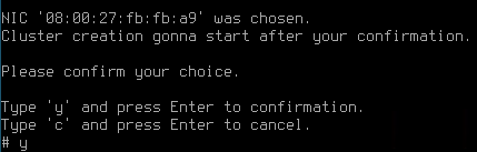
5. UTM will offer to change the name of the server. If you answer the question "Change server name?" positively, an inscription will appear with a suggestion to enter a new server name.
The minimum number of characters in the name is 2.
The maximum number of characters in the name is 42.
After entering a new name, press Enter to continue the dialog.
6. A message will appear that the cluster creation process has started.
You need to go to the web interface of the active node and perform the settings (see point Configuring Active Node). 3,600 seconds are allocated for this.
Configuring Active Node
To configure an active node in the SafeUTM web interface, follow these steps:
1. Go to Server Management -> High availability and click Configure active-passive cluster.
2. Confirm that the topology of your network corresponds to the diagram in the figure below: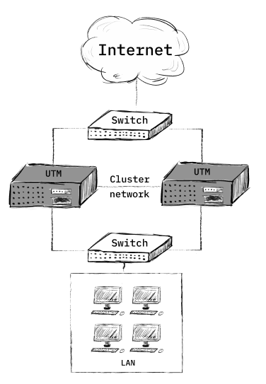
3. Select a network card to connect between nodes: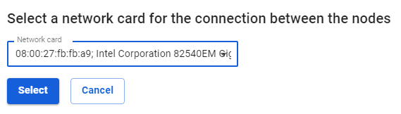
4. Match the network cards. To do this, select one network card in each column and click Match.
5. After applying the settings, the backup node will reboot, and the web interface of the active node will display information that communication with the server has been established.
Backup Node Capabilities:
By going to the local menu of the backup node, you will see that only the following items are available in the server management list:
- Cluster destruction
- Restarting the server
- Disabling the server
- Exit
At the same time, the active node has a fully functional interface and all functionality is available.
Cluster Destruction
You can remove the node from the cluster from the local menu or web interface. At the same time, the node which you are attempting to remove continues to work. The second node resets the settings to the state of the newly installed SafeUTM.
Destroying a cluster from the local menu
Cluster destruction from the web interface
- Go to the section Server Management -> High availability and click on Destroy cluster.
- A warning will appear.
- Click on Yes.
Node Update Procedure
In order to update UTM to the latest version in cluster mode, you need to do the following:
- Start updating the active node. During the update process, it will be rebooted. After the reboot, the backup node will become active, transferring the current traffic processing tasks to itself.
In this case, the cluster will not be operational, since both devices must have the same version of the system, identical up to the build number. - Wait for the active node to download the update and run it. After the update is completed, the cluster will be operational again.
Automatic Update
Updating the server is possible exclusively over the network. It is not possible to upgrade using the installation disk or USB flash drive.
Automatic Update
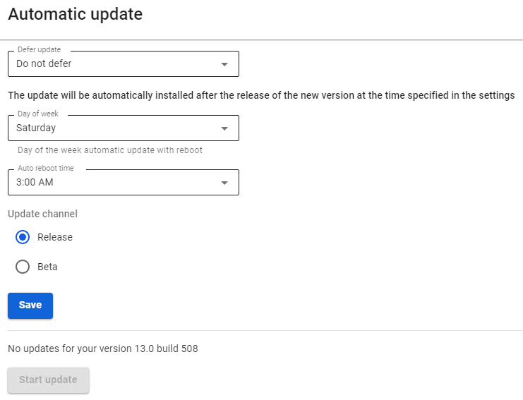
The automatic update parameters are configured in the section Server Management -> Automatic Update.
- Field Defer update – the time for which the update will be postponed (maximum period of 6 months).
- Field Day of week – the day of the week when the automatic update is started.
- Field Auto reboot time – allows you to select the time to start automatic updates.
- Field Update Channel – select Release or Beta channel allows you to update to stable versions. The Beta channel allows you to update to the latest beta versions of the product (the versions are relatively stable, but in some cases, the product may not work correctly). By default, the Release option is selected.
- Button Start update – starts forced update mechanism. If the button is inactive, there are no updates for your version.
When initiating a forced update, the update will be downloaded, after which a full reboot of the server will be required.
After the update procedure, the new version will be displayed in the upper-left corner of the local console and the administrator web interface.
Backup
Providing users with stable access to the Internet is the main task solved by the Internet gateway. But sometimes there are situations that lead to system failures and subsequent disruption of Internet access. Depending on the complexity of the failure, it may be necessary to completely reinstall the Internet gateway and restore data from backups. In this section, you will find the description of the backup-creating process for the SafeUTM Internet gateway.
The Internet gateway supports the following types of automatic backups:
- To a network file storage via FTP.
- To a network file storage over NetBIOS protocol.
- To the local hard drive.
To set up automatic backups, go to Server Management -> Backup -> Settings. A backup copy is created every day at the hour specified in the settings (it is recommended to choose nighttime to create a backup).
You can store backups for a week or a month.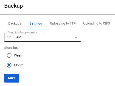
Backup to Remote File Storage via FTP
This type provides for writing backups to an FTP server. The key parameters required to set up a backup to an FTP server are described in the table below.
|
Parameter |
Description |
|
Server address |
The IP address of the remote FTP server where copies of the database will be hosted. |
|
Login |
Username for authorization on the FTP server. |
|
Password |
Password for authorization on the FTP server. |
|
Directory path |
The directory to which copies of the database will be written. |
Backup to Network File Storage Using NetBIOS Protocol (CIFS)
This type of backup involves writing a copy to the server using the NetBIOS protocol (CIFS). The key parameters required to configure a backup to a NetBIOS server are described in the table.
|
Parameter |
Description |
|
Server address |
The IP address of the remote NetBIOS server where copies of the database will be hosted. |
|
Login |
User name for authorization on a Windows network resource. |
|
Password |
Password for authorization on a Windows network resource. |
|
Directory path |
The directory to which copies of the database will be written. |
For a domain account, the format of the Login field should look like this: Domain_name/User_name. The Directory path must be specified in UNIX format. For example, in Windows OS, the directory opens at the following path \\192.168.1.1\dir_1\dir_2\backup, so in the field Directory Path dir_1/dir_2/backup must be specified.
Backup to Local Hard Drive
It is possible to upload a backup copy from the server or from a computer to the server using the web interface or local menu.
The backup management interface in the web interface is shown in the screenshot below.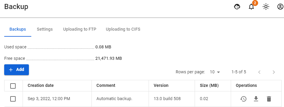
Managing backups via the local menu
- To create a new backup via the SafeUTM local menu, select item 9 and press Enter. Next, enter a comment for the backup and press Enter.
An example of creating a backup via the local menu is shown in the screenshot below: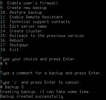
- To restore configurations from the backup, select item 10 and press Enter. Select a backup copy from the list (if there are several copies) by entering the item of the desired copy, and pressing Enter. To restore from a backup, you need to restart the server. Type y and then press Enter to restart.
An example of restoring from a backup via the local menu is shown in the screenshot below: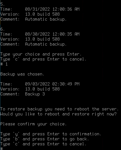
Terminal
Use the terminal only for diagnostics. Refrain from commands that modify files. The system is designed to be configured only via the web interface. SafeDNS is not responsible for the negative consequences of working with SafeUTM from the terminal. Technical support has the right to refuse service if it turns out that the operation of the system has been disrupted due to user actions in the terminal.
Main commands
- Network diagnostic utilities:
ping,host,nslookup,tracepath,tcpdump,arping,mtr - File manager:
mc - Viewing logs:
journalctl -u *service name*(for example,journalctl -u safe-routing-backend)
License
Licensing Scheme
At the moment SafeUTM license has two types of licenses:
- Free trial;
- Enterprise.
Both types of licenses can be acquired by contacting your SafeDNS manager.
Viewing license information
A detailed view of the server and license information is available by clicking on the eye icon in the Operations column of the Server + License table.
Detailed information about the license contains data about the license validity period, number of users, expiration date of updates, and technical support of the product.
Additional settings
Setting the time zone and collecting anonymous statistics.
The configuration is carried out via the web interface in Server Management -> Additional settings section.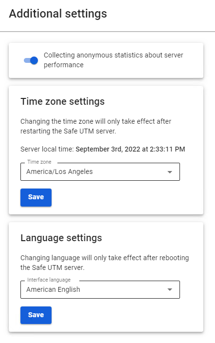
- Time zone settings - set the time zone in order to collect logs and statistics correctly.
The time zone change will take effect only after the SafeUTM server is restarted.
- Collecting anonymous statistics about server operation - enabling this parameter allows the server to send information about the modules used. In this case, information about users, traffic passing through the server, network interfaces, and server IDs and licenses are not sent.