Access to Remote Networks via Router on LAN
Deleting Direct Routing Between Router and LAN Hosts
Let's say there is a router in the local UTM network that establishes communication with other networks (often using a tunnel). UTM is the default gateway for network clients. You want to set up routing on UTM so that clients can access the remote network through the router. To do this, the router and the clients of the local UTM network must be in different subnets. Otherwise, there will be an effect of asymmetric routing, due to which part of the traffic from clients to the router will go through the gateway, and part will go directly from the router to the network subscribers. Different routing on different traffic sections will make it impossible for packets to pass between two LANs.
A variant of the incorrect topology of such a network where there is a direct or asymmetric routing between the router and the clients of the local network:
SafeUTM is the gateway for LAN 10.80.1.0/24. This network has a router with the IP address 10.80.1.2, which has access to the remote network 192.168.10.0/24. It is required to provide access of the 10.80.1.0/24 network hosts to the 192.168.10.0/24 network and back.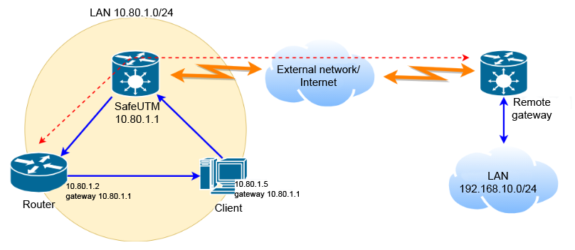 The red arrow indicates two-way communication of the router with a remote gateway (or also a router), through which access to the remote network
 192.168.10.0/24 is provided. This can be a tunnel to a gateway located on the Internet or a route to a router in a neighboring enterprise network.
The blue arrows indicate traffic sections from the hosts of the local UTM network 10.80.1.0/24 to remote network 192.168.10.0/24 through the UTM gateway with IP address 10.80.1.1 . Then the traffic goes through the router with the IP address 10.80.1.2, and a portion of the traffic returned to the LAN hosts from the router, bypassing UTM, which leads to the non-acceptance of such traffic by the LAN hosts.
In order for the scheme to work correctly, it is necessary to:
- Move the router to a separate LAN (DMZ) (for example,
10.90.1.0/24) to avoid direct routing between the router and LAN clients. - Configure the DMZ on UTM by adding another IP address to the local UTM interface
10.90.1.1/24, to whose LAN the router is connected. - On the router, configure the IP address from the address space of the new
10.90.1.2network. Specify an additional IP address configured on the local UTM interface from this10.90.1.1network as the gateway.
Physically, the router and LAN clients will be in the same segment, while having different IP addresses and gateways.
You can also physically isolate the UTM clients’ LAN and router by connecting an additional network card to SafeUTM. Set up an additional local interface on it and a separate IP address in this network. The gateway for the router will be the address configured on the additional local interface.
Physically, the router will be located in the segment of an additional network card. However, as a rule, a scheme with virtual isolation of networks based on a single physical interface is enough.
The network topology after the DMZ organization is based on the creation of an additional 10.90.1.0/24 network on the local UTM interface is shown in the diagram below: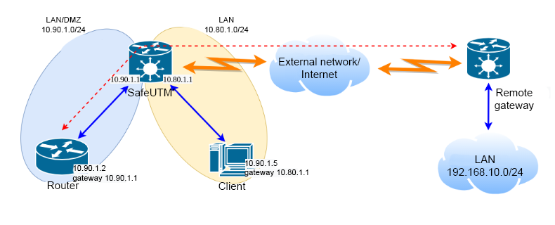
Required UTM Settings
Several virtual LANs on one physical local UTM interface is set up in Services -> Network Interfaces. It looks like this: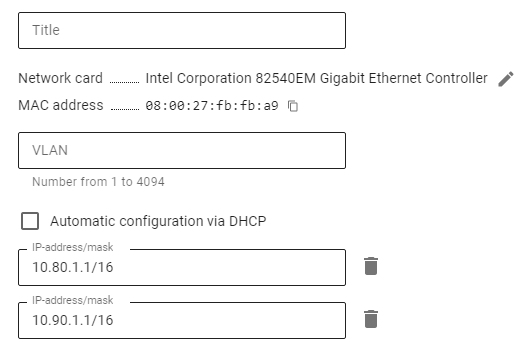
After isolating the router in the DMZ, you need to specify a route to the remote network on UTM.
The clients’ LAN has the address 10.80.1.0/24 , the router address in the DMZ is 10.90.1.2, and a remote network to which the router has access has the address 192.168.10.0/24. In this case, the UTM route will have the following parameters:
- Destination (DST): 192.168.10.0/24
- Gateway: 10.90.1.2
You can also add Source (SRC), in our case 10.80.1.0/24, but this is arbitrary. Now traffic between UTM networks (10.80.1.0/24 and 192.168.10.0/24) in all directions will be routed via UTM and router.
Always avoid specifying the 0.0.0.0/0 network in routes.
Settings on Client Machines
Hosts of the networks that the UTM now serves (10.80.1.0/24 and 10.90.1.0/24) are physically included in one ethernet segment. The gateway and DNS server for the hosts of these networks is the address corresponding to the network on the local UTM interface. For example, for a host with the address 10.80.1.10, the gateway and DNS will be 10.80.1.1, and for a host with the address 10.90.1.15, the gateway and DNS will be 10.90.1.1 .