Installation Process
System Requirements
Mandatory conditions for work with SafeUTM:
1. UEFI support.
2. Turn off Legacy boot mode, it may be called CSM (Compatibility Support Module).
3. Turn off the Secure Boot option in UEFI.
|
Hardware |
Minimum system requirements |
Note |
|
Processor |
Intel Pentium G/i3/i5/Xeon E3/Xeon E5 with SSE 4.2 instructions support |
Requirements may differ depending on network load and services used, as well as content filtering, antiviruses, and intrusion prevention system. The system requires at least 2 cores; a 4-core processor is better. |
|
RAM |
8 Gb (16Gb if the number of users is over 75) |
Requirements may differ depending on network load and services used, as well as content filtering, antiviruses, and intrusion prevention system. |
|
Disk subsystem |
HDD or SSD, capacity 64 Gb or more, with SATA, SAS. Additional HDD or SSD when using a mail server is required. |
Software RAID controllers are not supported (those integrated into the chipset or motherboard). Using hardware RAID controllers is not recommended. |
|
Network adapters |
One network adapter |
Gigabit (or 10G) Intel network cards are recommended. |
|
Additional |
Display and keyboard |
No preinstalled OS or additional software is required to install and run SafeUTM. SafeUTM is installed to a dedicated server from an installation USB-flash, a file system is automatically created and all necessary components are installed. |
In order to choose the best hardware platform for you please follow the guidelines on equipment choice for SafeUTM. The approximate hard drive capacity to store the information of about 1000 users for 1 year is 10-15 Gb.
Browser support for server administration web interface
All up-to-date versions of Firefox, Chrome, and browsers based on Chromium are supported. Internet Explorer is not supported.
Hypervisor support
Microsoft Hyper-V (2nd generation, Windows 2012R2 or higher), VMware, VirtualBox, KVM, Citrix XenServer. More information can be found here.
Configuration examples
Examples of several types of configurations depending on the number of users can be seen in the table below.
|
Hardware |
25 |
50-200 |
200-500 |
1000 |
2000 |
|
Processor |
Intel Pentium Gold G5400 or compatible |
Intel i3 8100 or compatible |
Intel i5, i7, Xeon E3, 3 GHz and up, or compatible |
Intel Xeon E3, E5 or compatible |
Intel Xeon or compatible 8-core one |
|
RAM |
8 Gb |
8 Gb |
16 Gb |
16 Gb |
32 Gb |
|
Storage space |
64 Gb |
64 Gb |
250 Gb |
500 Gb |
500 Gb |
|
Network adapters |
2 pcs. |
2 pcs. |
2 pcs. |
2 pcs. |
2 pcs. |
Performance data:
Configuration example: Intel Xeon E-2234, 16 GB DDR4, 1 GB LAN.
- Mode L3: TCP up to 1 Gbps, UDP up to 1 Gbps, HTTP up to Gbps.
- *Mode L7: TCP up to 550 Mbps, UDP up to 900 Mbps, HTTP up to 500 Mbps.
* - Mode L7: IPS modules, content filtering, application control, and antivirus scan are on.
Installation Options
You can install SafeUTM on a dedicated server or a virtual machine. It depends on the expected load and equipment capacity.
SafeUTM installation from a USB flash drive
SafeUTM can be installed from a flash drive by using an installation ISO file. This process is described in the Creation of boot USB flash drive article.
Installation on a dedicated server
In order to install the SafeUTM security gateway you need to follow these steps:
- Prepare hardware in accordance with technical requirements.
- Prepare a USB-flash drive with a capacity of over 2 Gb.
- Receive the ISO file from your manager.
- For safety reasons check the downloaded file checksum, which you can find on the SafeUTM downloads page in your personal account.
- Create the bootable USB-flash drive using the ISO file.
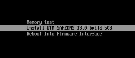
- In the computer’s BIOS settings choose "boot from USB-flash drive" and start the system installation from this USB drive. SafeUTM installer should appear on the screen as seen below.
Installation Process
Stage 1. Start of installation
Choose a disk for installation. To do this, enter the number of the disk you wish to use and press Enter.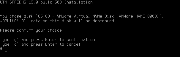
The system will warn about the loss of all data stored on the disk. We recommend that you make sure the disk does not contain any important information, as it will not be possible to recover it. The data loss alert can be seen in the screenshot below. To continue, type y and press Enter.
Now you need to select the time zone. Select the time zone you are in. To do this, type y and press Enter.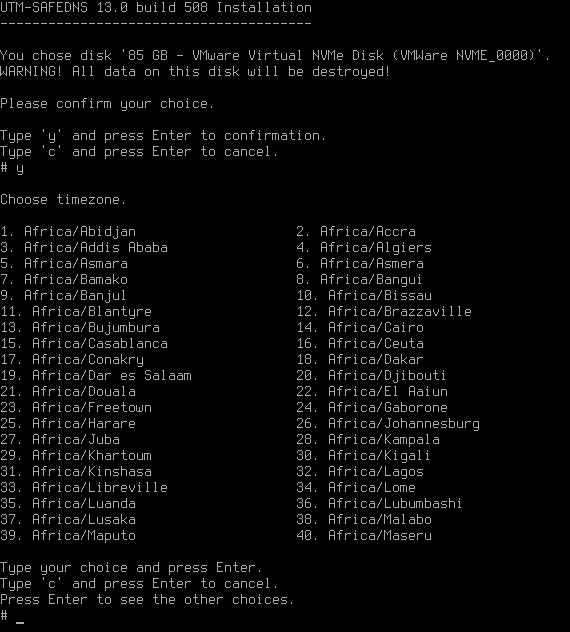
In the next dialog box, you need to set up a date and time. If the settings are correct, type y and press Enter.
If the current settings are incorrect, type n and put in the correct data, then press Enter.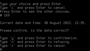
Then the system will perform disk subsystem tests necessary for installation:
- A partition table will be created and formatted.
- System files will be copied onto the disk.
- Basic system settings will be configured according to your computer configuration.
Don’t forget to eject the USB drive when restarting UTM so that the system doesn’t start booting from the installation drive.
After the server restarts, you will see a window with system info. An example of such a window can be seen below. To continue press any key.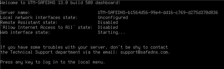
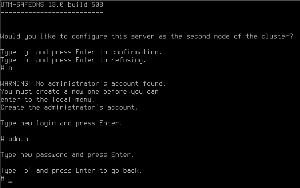
If you want to configure the server as the second node of the cluster, press y and then Enter. For more information about configuring clustering, see the High Availability article.
If the clustering setup is not required, press n and then Enter.
Stage 2. Creating admin’s account
Create an admin account. After typing in login press Enter and type in a new account password, then press Enter.
Admin password requirements:
- Minimum 10 symbols.
- Upper- and lower-case Latin letters.
- At least one digit
- Special characters (! # $ % & ' * + etc.)
If the password does not pass the security policy requirements, a notification about password unreliability will appear. You need to type in another password taking into consideration password requirements and press Enter.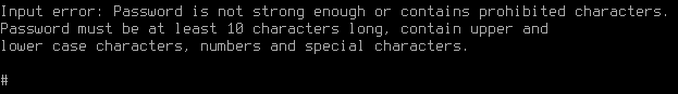
When the account has been created, press any key to switch to the local menu and type in data from the newly created admin’s account.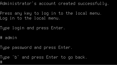
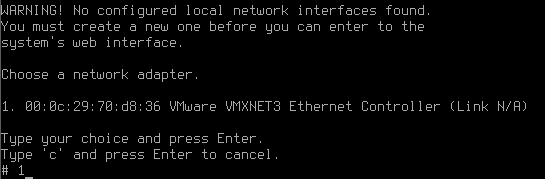
Stage 3. Network adapter setup
Now the system will suggest that you set up a local network interface. It is the interface to which all your enterprise network will be connected. Type in the network adapter number from the list and press Enter.
During local interface definition, you may encounter difficulties with NIC identification. Sometimes several adapters may have the same manufacturer. In such a case in order to avoid a mistake, you need to identify the device by its MAC address. Do not worry about making a mistake, you can change these settings later.
Type in the local IP address subnet mask as ip/mask and press Enter.
Next, if necessary, create a VLAN tag or leave the field empty and press Enter.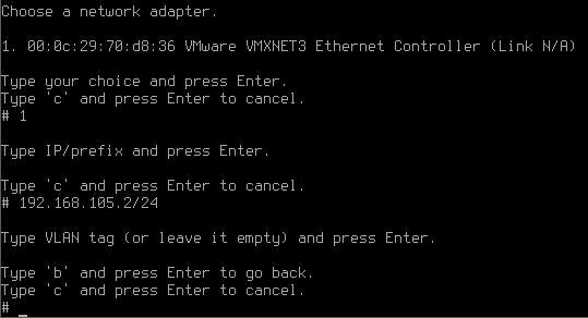
After creating a local interface, the server administration menu will open.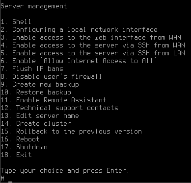
The next step is SafeUTM configuration. This process is described in the Initial configuration article.